3D-Printed Drone Assembly and Bench Checks
Tools
- Screw driver with matching bits
- Nut driver or wrench
- Multimeter
Warning: Remove all propellers before applying bench power
12 steps
Check parts and tools; keep power disconnected
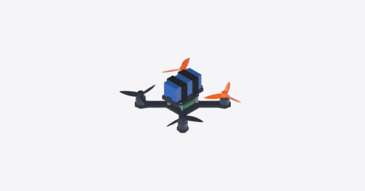
Start with the X-frame unpowered and all propellers off. This is a model-based fit and assembly sequence, not a release for flight. Parts marked fit model, fit only or clearance stand-in show position or envelope only.
- Frame and deck: X-frame, Removable battery deck, Front right spacer, Front left spacer, Rear right spacer, Rear left spacer; Button head screw ISO 7380-1 M3x8 5 through 8 (four) and Button head screw ISO 7380-1 M3x6 9 through 12 (four).
- Motors: Front right, Front left, Rear right and Rear left Aether 1404 4600 KV; 16 motor screw placements marked (fit only), four per motor. The four Gemfan 3016-3 clearance stand-ins are not installation hardware. Set any real propellers aside.
- Electronics: SpeedyBee F405 40A AIO fit model, RadioMaster RP1 V2 receiver fit model, RP1 thin receiver carrier; four Controller screws, four Controller nuts and four controller washers, one set per corner.
- Battery mounting: GNB battery cradle, Left battery cradle screw, Right battery cradle screw, Front battery strap (fit model), Rear battery strap (fit model) and GNB 4S 880 mAh LiHV fit model. Keep the actual pack disconnected.
- Tools: use a correctly fitting driver for each screw head, a correctly fitting nut driver or wrench for the Controller nuts, and a multimeter for unpowered electrical checks. Use a torque driver only with an approved torque and a matching bit. Select tooling against the actual hardware; bit and wrench sizes are not established by this procedure.
Use approved hardware and specifications for permanent assembly. If they are unavailable, limit the work to an unpowered fit check and do not force or modify parts.
Inspect the frame and fit the four spacers
Inspect the X-frame for cracks, layer separation, warping and damaged holes. Seat the four spacers on their matching corners above the frame. Insert the four ISO 7380-1 M3x8 button head screws (model suffixes 5 through 8) from below. Hand-start each screw and check that all four spacers seat flat. Do not substitute the shorter deck screws. Apply only the approved torque.
Mount the four Aether motors without propellers
Seat the four Aether 1404 4600 KV motors on their matching arm pads. Install four approved motor screws per motor from below. The model shows screw positions only; verify thread, length and engagement.
Before applying power, turn each motor bell by hand to check for rubbing or binding. Keep leads clear of moving parts and leave all propellers off.
Fit the controller stack before closing the deck
Use the SpeedyBee F405 40A AIO fit model as the placement reference for the actual controller. The model shows four controller washers under the frame, four Controller screws entering from below, and four Controller nuts above the board, one set per corner. The model shows a gap under the controller but does not identify the approved support or isolation hardware. Do not clamp the board across that gap or let hardware contact components or pads. Proceed with permanent installation only with the approved stack, board orientation and tightening specification.
Fit the receiver and check lead clearance
Fit the RP1 thin receiver carrier in the position shown above the controller. Place the receiver in the position shown by the RadioMaster RP1 V2 receiver fit model. Use the approved retention and insulation method; the model does not establish either. With the pack disconnected and the top open, check that leads and the antenna can be secured without pinching, abrasion or contact with the motor bells. Make electrical connections only against an approved wiring and polarity reference. The fit models do not establish pinout, antenna routing or electrical clearances.
Attach the cradle to the deck off the frame
Keep the battery disconnected. On the bench, align the GNB battery cradle with the Removable battery deck. With the deck still off the drone, fit the Left battery cradle screw and Right battery cradle screw from the underside. Hand-start both screws and tighten to the approved specification. Check that the cradle sits flat on the deck and does not rock.
Lower the deck assembly onto the spacers
Lower the Removable battery deck and attached GNB battery cradle together onto the four spacers. Make sure the deck sits flat and no electronics lead is trapped underneath. Leave the battery out so all four deck screw access openings are clear.
Fasten the seated deck from above
With the deck seated and the battery and straps out of the way, hand-start the four ISO 7380-1 M3x6 button head screws (model suffixes 9 through 12) through the cradle access openings from above. Check that the actual driver reaches each screw squarely before tightening. If access is blocked, stop rather than driving at an angle. Tighten to the approved specification and verify that the deck still sits flat on all four spacers.
Seat the disconnected battery in the cradle
Once the deck and cradle are secured, lower the undamaged, disconnected pack into the cradle as shown by the GNB 4S 880 mAh LiHV fit model. Keep both straps open and out of the way while seating the pack. Check that it sits flat and does not trap its leads. Leave the connector unplugged.
Secure and check both battery straps
With the pack seated and unplugged, close and tension the approved straps in the positions shown by the Front battery strap (fit model) and Rear battery strap (fit model). The rigid models show the closed positions only. Check that the pack cannot shift or lift and that neither strap pinches a lead or damages the pack. Leave the battery disconnected.
Perform final inspection and propeller-free bench checks
- Disconnect the pack. Physically verify that all four motor shafts are bare. The four Gemfan 3016-3 clearance stand-ins are hidden in this view to represent propellers removed.
- Inspect the printed frame and fastenings for damage or looseness. Verify that the motors turn freely by hand, the pack and electronics are secure, and no lead is pinched, abraded or able to touch a rotating part. Check battery polarity and screen for a short with a multimeter before power, using the approved wiring and test criteria.
- Do not energize if any fit, fastening, wiring or configuration check is unresolved. If all checks pass and an approved bench-test procedure and equipment are available, secure the drone on the bench, keep hands and loose items clear, and verify controller startup, receiver link, failsafe response, and motor assignment and direction against the approved setup. Do not run a powered test with propellers installed.
- Stop immediately for unexpected motion, abnormal heating, smoke or odor. At the end, disarm, disconnect the pack and leave the propellers off. This is not a flight release.
Install the propellers with the battery disconnected
After the propeller-free bench checks pass, disarm and physically disconnect the battery before handling the motors. Use the four Gemfan 3016-3 clearance stand-ins as position references only.
Fit the approved propeller at each corner only after verifying its handedness, orientation and retention hardware against the approved motor layout and mounting specifications. If any of those details or the tightening specification is unavailable, leave the propellers off. With the battery still disconnected, turn each propeller slowly by hand and check for contact with the frame, wiring or adjacent propellers. Leave the battery disconnected. This is not a flight release.