TwinWorks
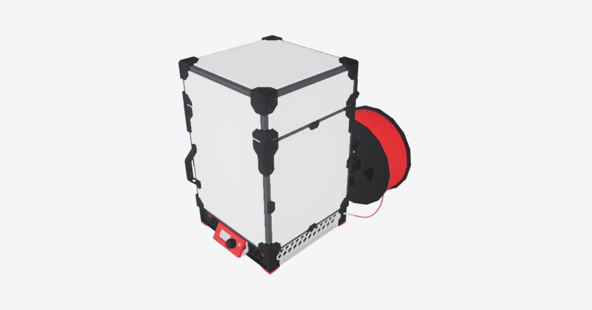
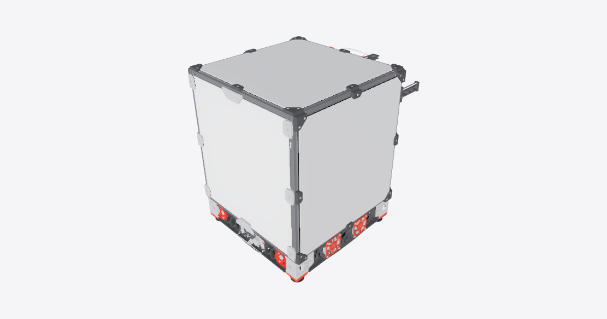
Voron 0.2 3D printer – 3D model preview

Voron 0.2 3D printer

Téa · 3D Printing · 3D model · Updated 14 Nov 2026

Open in 3D

  • Procedures2shared publicly
  • Views0all time
  • Rating–No ratings yet
  • Likes0from the Community

0 comments

Procedures

1 Frame and Z axis

Assembly · 10 steps · No ratings yet

10 steps
  1. Prepare the frame and Z-axis parts

    Voron 0.2 by the VORON Design team, github.com/VoronDesign. Licence: GPL-3.0. This guide is not official VORON documentation.

    Work with the printer unpowered on a flat, stable surface. Lay out the lower frame extrusions and their corner-joint screws. Match the access holes and extrusion slots to the positions shown. Remove loose debris from mating faces and slots. Keep the Z rails with their bearing carriages on the rails.

  2. Join and square the lower frame

    Bring the lower frame extrusions together in the arrangement shown, with the rear crossmember inset from the rear uprights. Insert the corner-joint screws through the access holes and engage the mating extrusion ends. Leave the joints loose enough to adjust.

    Keep the frame flat. Check adjacent members with a square and compare diagonals between the same reference points. Adjust until the corners are square and the diagonals agree, then snug the joints without twisting the frame.

  3. Fit the four corner uprights

    Fit the four corner uprights to the lower frame in the orientations shown. Engage the corner-joint screws and keep the uprights supported while the joints are loose.

    Check each upright against the lower frame with a square. Seat the joints fully and snug the screws while keeping the lower frame flat.

  4. Complete and square the frame

    Fit the upper frame members and the two inner Z-rail support uprights in the positions shown. Insert the captive nuts needed in the extrusion slots before closing access to those slots. Engage the frame screws without fully tightening them.

    Check the front, rear and side openings for square. Compare opposite diagonals within each opening, using matching reference points. Adjust the frame, then tighten the corner joints progressively while rechecking squareness and flatness. Keep the two Z-rail supports parallel.

  5. Fit and align both Z linear rails

    Place both Z linear rails on the inner support uprights with the bearing carriages facing the bed. Retain the carriages on their rails throughout handling. Seat the captive-nut strips in the extrusion slots and start the rail mounting screws.

    Align the rails parallel to the support uprights and to each other. Tighten the mounting screws progressively without pulling either rail sideways. Fit the rail stops in the positions shown. Slide each carriage gently within the retained rail length and check for smooth movement; do not run a carriage off a rail.

  6. Fit the Z motor and integrated lead screw

    Fasten the Z motor with its integrated lead screw to the motor mount using the mounting screws shown. Position the motor assembly beneath the rear lower crossmember and engage the frame-mounting screws and captive nuts.

    Keep the lead screw between and parallel to the Z rails. Seat the mount without bending the screw and snug its fasteners. Leave the motor unpowered and its wiring clear of the moving parts.

  7. Fit the Z endstop and bracket

    Fit the Z endstop bracket to the left Z-rail support in the position shown. Engage its frame screws and captive nuts. Secure the endstop switch to the bracket with its two small screws, without distorting the switch housing.

    Check that the switch actuator is free to move and lies in the path of the descending bed carriage. Keep the switch terminals and cable clear of the rail and lead screw. Do not power or home the printer during this mechanical assembly.

  8. Build and attach the bed carriage

    Join the three bed-support extrusions with the left and right rear bed mounts, the front bed mount and the lead-screw nut block. Seat the captive nuts and use the bed-support screws shown, leaving adjustment available.

    Support this bed carriage and align the rear mounts with both rail carriages. Start the eight carriage attachment screws without pulling the rails out of parallel. Engage the lead-screw nut by turning the screw gently into the nut, rather than forcing the nut sideways. Secure the nut to its block with the mounting screws.

    With the carriage supported, turn the screw slowly by hand to check movement. Adjust the rail and motor alignment if resistance increases, then tighten the carriage and motor-mount fasteners progressively. Never use motor power to overcome binding.

  9. Fit the spring-mounted bed

    Support the bed plate assembly above the bed carriage with the heater underneath and the removable build surface uppermost. Fit the three bed screws, washers, springs and adjustment knobs in the arrangement shown. Start all three supports before loading any one of them.

    Turn the adjustment knobs to retain the plate with all three springs under light compression. Keep the plate approximately level, with adjustment remaining at every support; do not compress the springs solid. Keep the heater leads clear of the screw and rails and allow enough slack for vertical movement. Leave the heater disconnected.

  10. Check frame squareness and free Z travel

    Recheck the frame corners, joint seating and matching diagonals after tightening. The frame must sit flat without rocking, and the rail supports must remain parallel.

    Keep power disconnected. Support the bed and turn the lead screw slowly by hand to raise and lower the bed through the available mechanical travel. Keep both bearing carriages on their rails and stop before reaching either end. Check for smooth movement without tight spots, carriage skew, lead-screw bowing or contact with the frame.

    Approach the Z endstop slowly and check that the carriage operates the switch before any rigid parts collide. Stop immediately if motion binds or the switch is missed; correct alignment and repeat the checks. Check that the heater leads remain clear and unstretched. Leave the bed supported in a stable position. Electrical endstop testing, powered homing and bed tramming are not part of this mechanical check.
2 XY motion and belts

Assembly · 10 steps · No ratings yet

10 steps
  1. Prepare the open frame

    Voron 0.2 by the VORON Design team, github.com/VoronDesign. Licence: GPL-3.0. This guide is not official VORON documentation.

    Start with the frame assembled, stable and unpowered. Leave the enclosure, top cover and complete toolhead off while building the XY motion.

    Check that the upper frame is square before attaching the motion parts. Identify the rear A and B drives, front idlers, two side Y rails, X crossbeam and toolhead carriage. Keep the two belt paths separate throughout assembly.

  2. Build and fit the rear A drive

    Build the rear A drive with its motor, pulley, upper and lower brackets, bearing stacks, washers and spacer in the arrangement shown. Fit the pulley to the motor shaft and leave its grub screws accessible for belt alignment.

    Seat the drive at the rear corner shown. Fit its frame mounting screws after seating the brackets, then secure the motor and bracket hardware without distorting the printed parts. Leave the tensioner backed off with its threads engaged.

    Turn the pulley and each bearing stack by hand. They must rotate without rubbing the brackets. Set the final pulley height when fitting the A belt.

  3. Build and fit the rear B drive

    Build the rear B drive with its motor, pulley, upper and lower brackets, bearing stacks, washers and spacer. Use the B bracket arrangement shown rather than copying the A assembly's belt height.

    Seat the drive at the other rear corner. Fit the frame mounting screws after seating the brackets and secure the motor and bracket hardware. Leave the tensioner backed off with its threads engaged.

    Check that the pulley and bearing stacks turn freely. Keep the grub screws accessible and set the final pulley height when fitting the B belt.

  4. Build and fit both front idlers

    Assemble both front idlers with their lower and upper housings, bearing stacks, washers and cam locks in the arrangement shown. Keep the A and B housing arrangements on their respective sides.

    Seat the housings at the front corners before fitting the frame mounting screws. Secure the bearing axle hardware while keeping the bearings free to rotate. Engage the cam locks and check that both assemblies are retained.

    Spin the bearings by hand. Correct any trapped washer, pinched stack or housing rub before fitting a belt.

  5. Fit and align the two Y rails

    Fit the two Y rails to the inside faces of the upper side frame members, with their bearing blocks retained on the rails. Match the orientation and fore-and-aft position shown. If the rails are already fitted, check their alignment instead of removing them.

    Engage the rail screws in the backing nuts or nut strips before tightening. Align each rail straight along its mounting face and tighten progressively without bowing it. Keep the rail stops fitted so the bearing blocks cannot run off the ends.

    Move both bearing blocks gently through their available travel. Each must slide smoothly before the X crossbeam is attached.

  6. Assemble and square the X gantry

    Build the X gantry from the crossbeam, left and right end joints, spacers and bearing stacks shown. Fit the X rail to the crossbeam with its bearing block retained on the rail. Secure the rail progressively while keeping it straight.

    Support the crossbeam between the Y bearing blocks. Seat both end joints and start their bearing-block mounting screws before tightening either side fully.

    Set both ends the same distance from matching fixed frame references so the crossbeam is square to the Y rails. Tighten the joint mounting screws progressively, then move the gantry gently front to rear. Correct alignment if it racks or binds; do not force it.

  7. Fit the toolhead carriage

    Fit the toolhead carriage body and support in the orientation shown on the X rail bearing block. Keep the bearing block on the rail throughout this operation.

    Start all four carriage-to-bearing-block screws, then tighten them progressively so the carriage seats evenly. Leave the belt attachment areas accessible and leave the remaining toolhead components off until belt routing is complete.

    Slide the carriage gently across the available X travel. Check for rubbing, rocking or tight spots and correct the seating before adding belt tension.

  8. Route the lower A belt

    Keep the gantry square and near the middle of its travel. Route the A belt in the lower belt plane shown, following its highlighted path through the rear drive guides, front idler and gantry guide bearings.

    Trace the entire path before retaining the belt ends at the carriage: use the A motor pulley for drive engagement, keep the belt teeth engaged with the pulley, keep the belt flat and untwisted, and keep each run centered between its guide flanges. Do not change belt planes at the crossings.

    Align the motor pulley with the belt run and secure its grub screws, with one bearing on the shaft flat where present. Seat and retain both belt ends in the carriage attachment features, taking up loose slack without applying final tension.

  9. Route the upper B belt

    Route the B belt in the upper belt plane shown. Follow its highlighted path through the B motor pulley, rear guide bearings, front idler and gantry guide bearings. Keep the gantry square while taking up slack.

    Trace the complete route and retain both belt ends at the carriage. Keep the belt untwisted, the teeth engaged with the motor pulley and the runs centered between the guide flanges. The A and B belts must remain in their separate planes without touching where their paths cross.

    Align the B pulley with its belt run and secure its grub screws, with one bearing on the shaft flat where present. Check both carriage attachments before applying final tension.

  10. Balance belt tension and check free movement

    Adjust the A and B tensioner knobs in small alternating increments to remove slack without pulling the gantry out of square. Compare belt deflection only on equal-length free spans under the same light finger pressure; aim for similar response rather than relying on equal knob turns.

    Recheck that both gantry ends are equally positioned against matching frame references. If the crossbeam skews, release tension and correct its alignment before continuing.

    With power disconnected, move the carriage slowly across X and move the gantry slowly front to rear through the available travel. Both axes must move smoothly without binding, belt rubbing, tooth skipping or contact between the two belts. Stop and correct any fault instead of forcing movement.

    Check that pulley grub screws, frame and rail screws, carriage attachments and belt ends are secure. Recheck squareness and even tension after cycling the motion. Leave the enclosure and remaining toolhead assembly for their assembly stages.

Related products