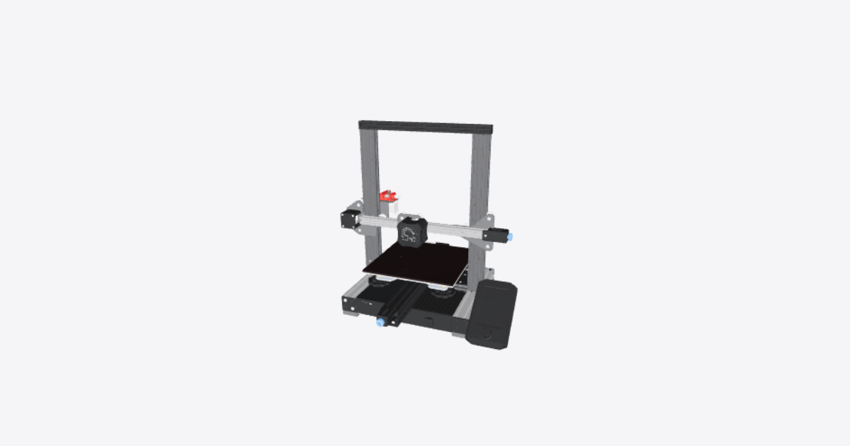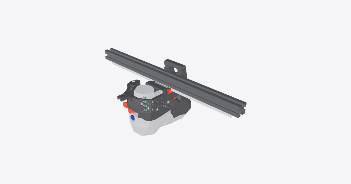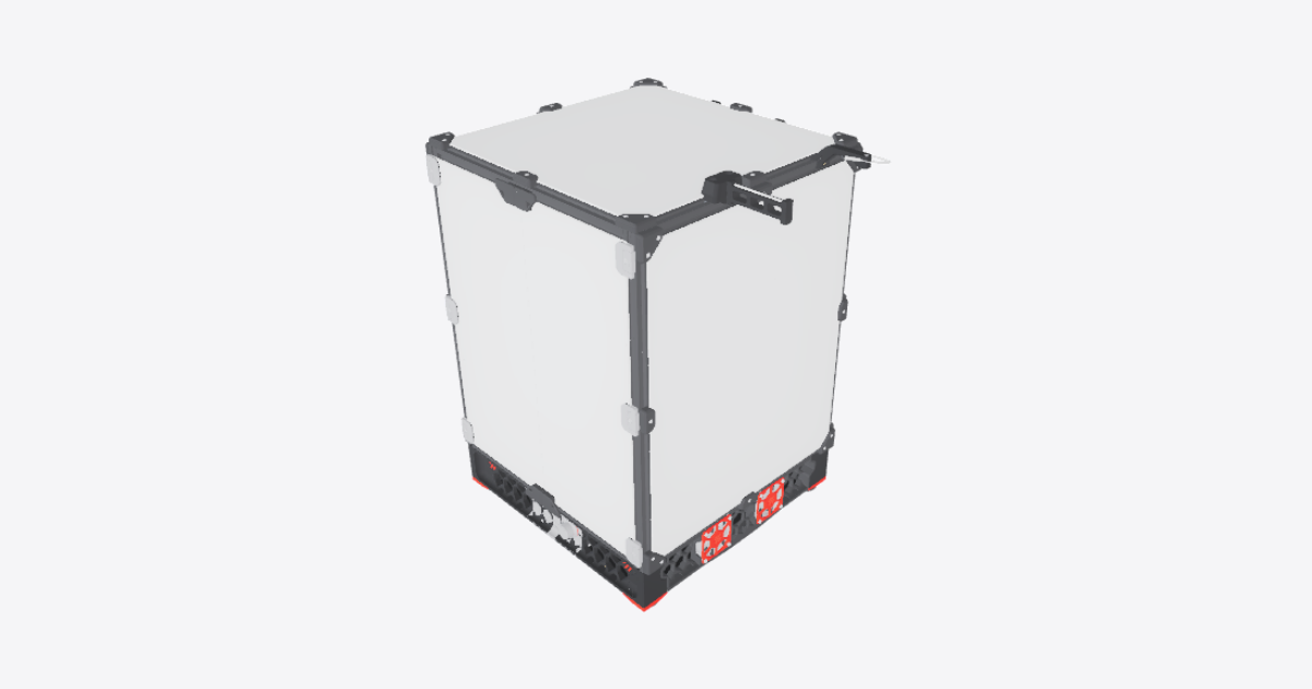
1 Frame and Z drives
10 steps
Assemble the lower frame and corner uprights
Voron Trident by the VORON Design team, github.com/VoronDesign. Licence: GPL-3.0. This guide is not official VORON documentation.
Work on a flat, stable surface with the printer unpowered. Lay out the four lower frame extrusions and the four corner uprights in the orientation shown. Put the lower rear extrusion with the central access hole at the back.
Join the lower extrusions to the corner uprights with the corner screws. Seat the extrusion ends flush against the uprights, start the screws by hand through the access holes, and leave the joints adjustable. Check that the lower frame rests flat without rocking.
Complete the upper frame and rear rail support
Join the four upper frame extrusions to the corner uprights with the upper corner screws. Keep the top joints adjustable while seating the extrusion ends flush.
Fit the rear central upright to the lower rear extrusion with its mounting screw. Fit the upper rear braces and their screws in the arrangement shown, with the rail mounting face toward the inside of the frame. Keep the rear upright straight and leave the braces adjustable until the frame is square.
Square and tighten the frame
Check the lower frame, upper frame and corner uprights before tightening the frame joints. Compare both diagonals of each rectangular face using the same reference points. Check that adjacent extrusions are perpendicular, the joint faces are flush, and the frame sits flat without twist.
Adjust the loose joints until the diagonals match and the corners are square. Tighten the corner screws progressively, alternating between opposite corners rather than fully tightening one corner first. Secure the rear central upright and upper braces, then repeat the squareness and flatness checks. Correct any movement introduced during tightening before fitting the Z components.
Fit and align the three Z linear rails
Fit the left, right and rear Z linear rails to their frame uprights in the positions shown, with their carriage blocks retained on the rails. Do not slide a carriage block off the end of its rail.
Engage the rail screws with the slot nuts by hand. Align each rail straight along its extrusion without pulling it sideways with the screws. Tighten the screws progressively while checking that the carriage block still slides smoothly. Fit the two side rail stops in the positions shown. Check all three carriage blocks for smooth travel without tight spots.
Assemble and fit the left Z motor and lead screw
Seat the left Z motor with its lead screw in the left motor mount. Install the motor screws evenly, supporting the motor body rather than loading the lead screw.
Place the motor mount on the lower left frame rails in the orientation shown. Engage the mount screws with their slot nuts and align the lead screw with the left Z carriage position. Secure the mount without bending the screw to meet the carriage. Fit the motor cover and its screws. Leave the motor disconnected.
Assemble and fit the right Z motor and lead screw
Seat the right Z motor with its lead screw in the right motor mount. Install the motor screws evenly while supporting the motor body.
Place the motor mount on the lower right frame rails as shown, using the right-hand arrangement rather than copying the left mount's orientation. Engage the mount screws with their slot nuts and align the lead screw with the right Z carriage position. Secure the mount without forcing the screw sideways. Fit the motor cover and its screws. Leave the motor disconnected.
Assemble and fit the rear Z motor and lead screw
Seat the rear Z motor with its lead screw in the rear motor mount and install the motor screws evenly.
Fit the mount to the lower rear frame rail below the rear Z carriage. Engage the mount screws with their slot nuts, align the screw with the carriage position and secure the mount. Fit the rear motor cover and its screws. Check that all three lead screws stand straight beside their corresponding rails without being pulled toward a mounting hole. Leave all motors disconnected.
Fit the lead-screw nuts, Z supports and bed frame
Turn the three lead-screw nuts onto their corresponding screws by hand, keeping the threads aligned. Bring the nuts to a similar height while supporting the carriage assemblies.
Fit the left, right and rear Z carriage brackets to the rail carriage blocks. Secure the lead-screw nut flanges and carriage cover plates with their screws. Assemble the three bed support joints with their spherical bearings, retaining screws and nuts in the arrangement shown. Keep the joints free to articulate rather than clamping them rigidly.
Join the two bed frame extrusions into a T with the bed frame joining screw. Fit the crossmember to the left and right bed supports and the stem to the rear support using the support screws and slot nuts. Support the frame throughout fitting. Turn the lead screws by hand as needed to bring the three supports to a common height, then secure the frame without drawing misaligned parts together with the screws.
Fit the bed stack to its support frame
With the heater unpowered and the bed cool, prepare the bed stack in the arrangement shown: heater beneath the aluminium bed plate, magnetic sheet on top, and flexible build sheet above it. Keep the thermal fuse and protective-earth attachment on the underside clear of the supports. Do not connect or energize the heater during mechanical assembly.
Fit the three bed spacers between the plate and bed frame. Support the plate, align its three mounting positions with the slot nuts, and install the bed mounting screws by hand before tightening them evenly. Do not force the plate flat by tightening one mount against a misaligned frame.
Seat the flexible build sheet flat on the magnetic surface. Keep heater and sensor leads out of the screws, lead screws and rail paths, with enough free length for bed movement.
Check frame squareness and smooth bed movement
Recheck the frame diagonals, corner squareness and joint seating after fitting the Z drives and bed. The frame must remain flat and untwisted, with all frame, rail and motor mounting screws secure.
Keep the printer unpowered and support the bed. Slowly turn the three lead screws by hand in small, matched increments to raise and lower the bed through its unobstructed mechanical travel. Keep the three supports at similar heights, keep carriage blocks on the rails, and stop before any hard stop or contact. Do not push down on the bed or force a screw through resistance.
Check for smooth movement without binding, scraping, abrupt changes in resistance or visible sideways deflection of a lead screw. Check that the support joints articulate and the heater leads remain clear throughout the movement. If a tight spot appears, stop, support the bed, correct the rail, nut or motor alignment, retighten the affected mounts and repeat the check. Leave the bed securely supported and the printer unpowered.