TwinWorks
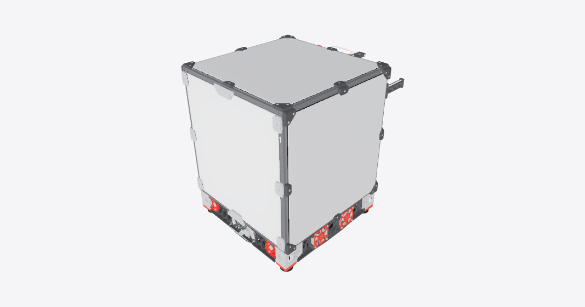
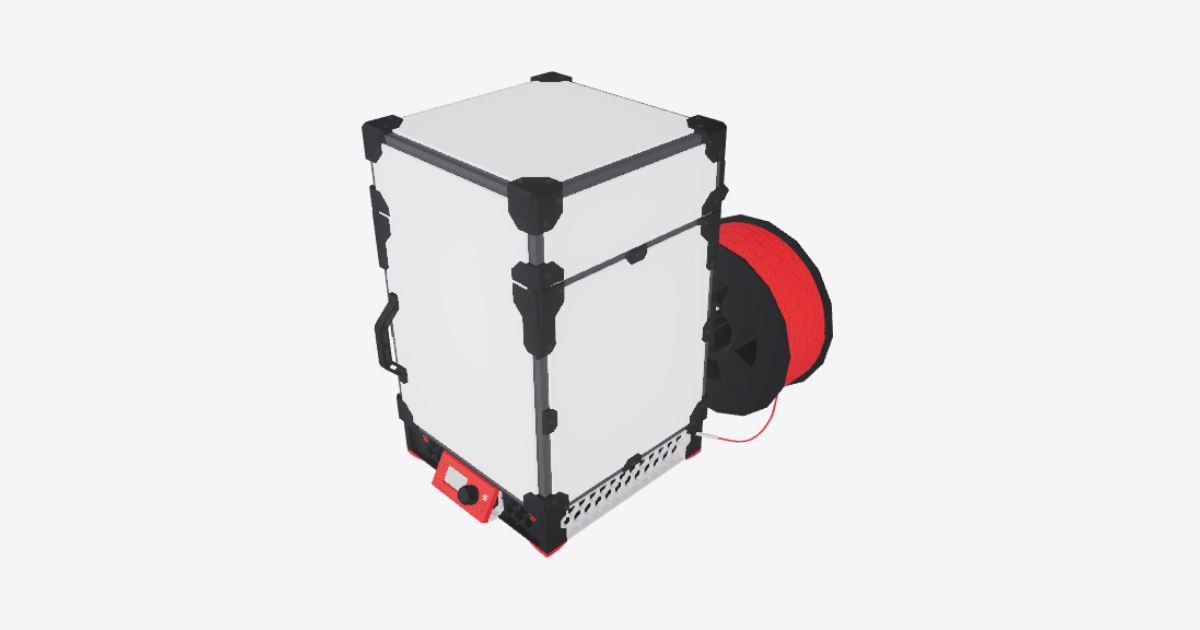
Voron 2.4 3D printer – 3D model preview

Voron 2.4 3D printer

Téa · 3D Printing · 3D model · Updated 14 Nov 2026

Open in 3D

  • Procedures2shared publicly
  • Views0all time
  • Rating–No ratings yet
  • Likes0from the Community

0 comments

Procedures

1 Frame and Z drives

Assembly · 10 steps · No ratings yet

10 steps
  1. Build the bottom frame

    Voron 2.4 by the VORON Design team, github.com/VoronDesign. Licence: GPL-3.0. This guide is not official VORON documentation.

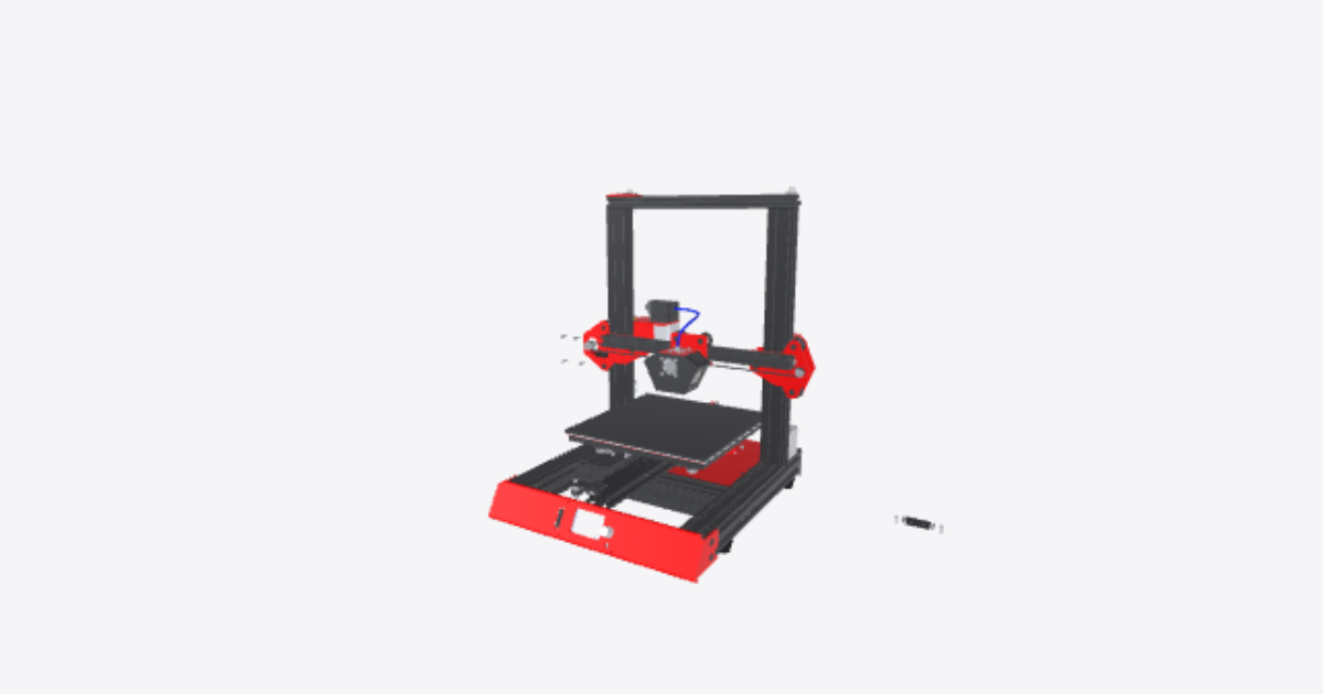
    Work on a flat, stable surface with the printer unpowered. Arrange the four bottom frame extrusions in the orientation shown. Engage the corner-joint screws in the extrusion ends and leave them loose enough to adjust. Seat the extrusion ends flush, check each corner with a square and compare the two diagonals. Adjust the rectangle until the diagonals match, then tighten the corner joints progressively without pulling the frame out of square.

  2. Fit the uprights and top frame

    Fit the four vertical extrusions to the bottom frame, with their rail-mounting faces oriented as shown. Engage the lower corner-joint screws loosely. Assemble the four top frame extrusions and lower them onto the uprights. Engage the upper corner-joint screws. Keep the ends flush and the uprights seated while leaving the joints adjustable for squaring. Support the frame so it cannot tip while the joints are loose.

  3. Square and secure the frame

    Stand the frame on the flat work surface. Compare the two diagonals of the top and bottom rectangles and of each vertical face. Check the corners with a square and check that the frame does not rock. Adjust the joints until the opposing diagonals match and the uprights are square to the base. Tighten the corner-joint screws progressively, working around the frame. Repeat the diagonal and squareness checks after tightening; correct any movement before fitting the bed or Z drives.

  4. Fit the fixed-bed supports

    Fit the two bed-support extrusions across the lower frame at the positions shown. Engage their end-joint screws and fit the four corner brackets with their screws, shims and extrusion nuts. Align the supports parallel to one another and in the same plane, with the bed mounting points facing upwards. Tighten the support joints and brackets progressively. Check that both supports are secure and that the main frame remains square.

  5. Mount the fixed bed

    Keep the bed heater disconnected. Support the bed assembly with its heater underneath and its build surface facing upwards. Lower it onto the bed supports in the orientation shown, keeping the heater and thermal-fuse leads clear of the frame and mounting hardware. Engage the mounting screws and knurled spacers at the modelled mounting points. Tighten progressively without bending the plate. Check that the bed sits securely on its supports, does not rock and has no trapped leads. Do not energize the heater during this mechanical assembly.

  6. Fit the four corner Z drives and motors

    Position the four Z drive units at the lower frame corners, matching each handed housing to the orientation shown. Each unit includes its motor, motor mount, short reduction belt, pulley shaft, bearings and drive pulley. Seat the housings and base plates against the frame and engage the mounting screws with the extrusion nuts. Tighten the frame attachments progressively without distorting the housings. Check that the short belts are seated on their pulleys, the pulley fasteners are secure and each drive turns smoothly by hand with power disconnected. Keep the motor leads clear of the pulleys and the future vertical belt runs.

  7. Fit the four vertical Z rails

    Fit the four Z linear rails to the inward-facing mounting surfaces of the uprights in the positions shown. Engage the rail screws with the extrusion nuts loosely before aligning each rail parallel to its upright. Keep the rail carriages on their rails and prevent them from sliding off either end. Tighten the screws progressively along each rail while maintaining alignment. Move each carriage through its available travel by hand and check for smooth movement without tight spots.

  8. Fit the four upper Z idlers

    Fit the four upper Z idler units at the top frame corners in the handed orientations shown. Engage their frame-mounting screws with the extrusion nuts and align each idler with the belt path to the drive below. Leave adjustment travel available in each tensioner. Tighten the frame attachments, then check that the idler pulleys turn freely and that the belt passages are clear. Do not clamp the pulley bearings so tightly that they bind.

  9. Route the four Z belts to the gantry

    With the gantry assembled, keep it supported evenly at all four corners while attaching the Z belts. Do not rely on an unsecured belt to hold the gantry. Route each of the four Z belts around its lower drive pulley and upper idler, following the installed route shown. Keep each belt untwisted, its teeth engaged with the toothed pulleys and both vertical runs clear of the frame. Seat the belt ends in the gantry belt clamps and secure the clamp screws without crushing the belt. Take up slack gradually at all four corners, keeping the gantry supported and level. Confirm that every clamp grips its belt before removing any support.

  10. Equalize Z belt tension and check the assembly

    Keep the printer unpowered and the gantry supported against dropping. Set the gantry level relative to the frame. Compare the four Z belts over equal free span lengths: apply the same light sideways force at the centre of each span and compare deflection. Adjust the upper tensioners in small increments until all four belts have equal tension, without pulling the gantry out of level. Check that the belts remain centred and that all clamp screws are secure. With the gantry supported evenly, move it slowly through the available vertical travel and check for rubbing, binding or belt slack. Recheck equal belt tension at the same gantry position. Finally check frame squareness, bed security and all four drive attachments again. Leave the heater and motors disconnected for subsequent electrical work.
2 Gantry and belts

Assembly · 10 steps · No ratings yet

10 steps
  1. Lay out the gantry extrusions

    Voron 2.4 by the VORON Design team, github.com/VoronDesign. Licence: GPL-3.0. This guide is not official VORON documentation.

    Work with the printer unpowered. Support the gantry parts on a flat surface. Leave the enclosure, cable chains and complete toolhead off during this assembly.

    Lay out the rear gantry extrusion and both side gantry extrusions in the orientation shown, with the open end toward the front. Fit the slot nuts needed by the corner units and rails before closing access to the slots. Keep the extrusion ends clean and the mating faces seated.

    The 3D views show staged assembly positions, not insertion paths. Thread flexible belts through the hardware rather than trying to install them as rigid loops.

  2. Assemble and position the four Z joints

    Build the four Z joints from their upper and lower bearing blocks, lower belt clamps, bearing carriages, screws and nuts. Keep each joint's hardware together and reproduce the orientation shown. Put the joint with the magnet housing at its matching rear corner.

    Locate the joints at the four gantry corners. Start the bearing-block and gantry-attachment screws without forcing the blocks out of alignment. Keep the belt-clamp openings accessible for the Z belts. Support the gantry independently; do not let it hang from loose joints or belt clamps.

  3. Build and fit the rear B drive

    Assemble the rear B drive at the rear-left corner, viewed from the printer front. Fit the motor to the lower housing and fit its toothed drive pulley. Install the three idler stacks with their shims in the order shown in the 3D view, then close the upper housing.

    Align the pulley groove with its belt plane before securing the pulley screws. Tighten the housing and axle screws progressively, checking that every idler turns freely and no printed part distorts.

    Seat the drive against the rear and side extrusions and engage its mounting screws with the slot nuts. Keep the upper Z-belt clamp accessible. Leave the corner adjustable until the gantry is squared.

  4. Build and fit the rear A drive

    Assemble the rear A drive at the rear-right corner, viewed from the printer front. Fit the motor, toothed drive pulley and three idler stacks between the lower and upper housings, retaining the modeled shim order.

    Align this pulley to its own belt plane; do not assume its height is identical to the B-drive pulley. Secure the pulley screws and tighten the housing progressively while checking that the idlers remain free.

    Engage the drive mounting screws with the extrusion slot nuts and seat both mating faces. Keep the Z-belt clamp and motor cable exit accessible. Leave the corner adjustable for squaring.

  5. Assemble the front idlers and square the gantry

    Assemble both front idlers with their upper and lower housings, sliding tensioners, bearing stacks, tensioning screws and washers. Fit the A idler at the front-right corner and the B idler at the front-left corner, viewed from the printer front.

    Engage the mounting screws in the side-extrusion slot nuts. Back the tensioning screws out enough to leave adjustment travel while keeping them engaged. Check that the bearing stacks rotate freely and the tensioners move without sticking.

    With the gantry supported flat, seat the rear corner faces and compare the two corner-to-corner diagonals using the same reference points. Adjust until the diagonals match, then tighten the corner mounting screws progressively and recheck. Keep the four Z joints aligned without twisting the gantry.

  6. Fit the Y rails and X/Y joints

    Fit both Y rails along the side extrusions in the orientation shown. Engage the rail screws with their slot nuts and tighten progressively while keeping each rail straight and aligned with its extrusion.

    Assemble the left and right X/Y joints with their bearing blocks, toothed idlers, smooth idler stacks, shims, axle screws and nuts. Preserve the distinct upper and lower belt planes. Attach the joints to the corresponding Y bearing blocks with their mounting screws.

    Retain the bearing blocks on their rails throughout handling; do not slide a block off an unprotected rail end. Move each joint gently along its rail to check for binding. Leave the X-beam attachment screws loose enough for alignment in the next step.

  7. Fit the X beam, X rail and toolhead carriage

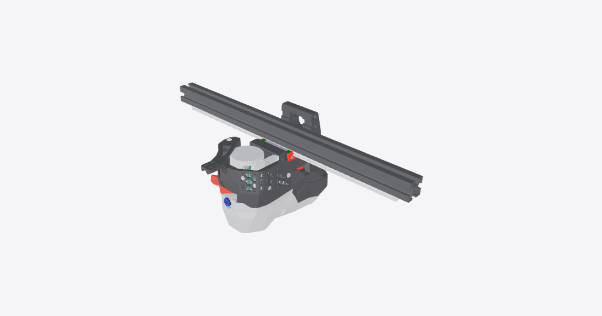
    Fit the X rail to the X beam using its mounting screws and slot nuts. Keep the rail straight as the screws are tightened progressively. Keep the X bearing block on the rail and attach the toolhead carriage frame to it with the carriage screws; leave the complete toolhead off.

    Place the beam between the X/Y joints and start the beam mounting screws. Bring both ends to the same fore-and-aft position, keep the beam perpendicular to the Y rails and tighten without pulling the rails out of parallel.

    Move the carriage across X and the beam along Y by hand. Both ends of the beam must travel together without racking, tight spots or contact with the corner units. Correct alignment before fitting the belts. Keep the carriage belt clamps accessible.

  8. Route and clamp the A belt

    Center the X beam and carriage, with the front tensioners backed off. Identify the A belt by its highlighted route and the rear A motor pulley, not simply by the side on which a loose belt end lies.

    Start at one A-belt clamp on the toolhead carriage. Thread the belt through the adjacent X/Y-joint idlers, along the side runs and around the front and rear idlers and A-drive pulley, following the highlighted loop continuously back to the other carriage clamp. Keep it in its own height plane through every turn.

    Keep the belt untwisted. Engage the toothed face with toothed pulleys and let the smooth back run over smooth idlers. Seat the belt between the flanges without rubbing the housings. Pull out loose slack and secure both ends in the carriage clamps with full tooth engagement, leaving adjustment allowance. Do not trim the tails yet.

  9. Route and clamp the B belt

    Route the B belt from one of its carriage clamps through the X/Y-joint idlers, the front and rear idlers and the rear B motor pulley, then back to its other carriage clamp. Follow the highlighted B loop continuously and retain the separate belt plane shown by the model.

    Keep the toothed face on toothed pulleys and the smooth back on smooth idlers. Check every concealed turn before closing access. The two belts must not twist, exchange height planes or touch one another.

    Remove loose slack and secure both B-belt ends in the carriage clamps with full tooth engagement. Leave adjustment allowance and keep the tails untrimmed. Move the carriage and beam gently to confirm that both belts remain seated before applying final tension.

  10. Balance belt tension and check square, free travel

    With the X beam and carriage centered, adjust the two front tensioners in small alternating increments. Remove slack without bowing the gantry or overloading the idlers. Compare the A and B belts on equal-length free spans with the carriage in the same position, using the same checking method for both. Equal tensioner screw turns alone do not establish equal belt tension.

    Recheck gantry diagonals and that both ends of the X beam remain square to the Y rails. Correct racking by releasing and redistributing belt tension before retightening; do not force the beam square against heavily tensioned belts.

    With power still off, move the carriage and beam slowly through their available X and Y travel, including the corners. Check that both belts track centrally, no belt rubs another belt or housing, the idlers turn freely and the belt clamps do not slip. Stop and correct any binding or uneven resistance.

    Recheck the drive pulley screws, corner fasteners, rail screws and carriage clamps. Secure the belt tails clear of moving parts only after routing, tension and free travel remain stable. Keep the gantry supported until all four Z attachments are secure.

Related products