TwinWorks
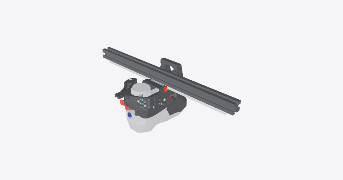
Voron Stealthburner toolhead – 3D model preview

Voron Stealthburner toolhead

Téa · 3D Printing · 3D model · Updated 13 Nov 2026

Open in 3D

  • Procedures3shared publicly
  • Views0all time
  • Rating–No ratings yet
  • Likes0from the Community

0 comments

Procedures

1 Printhead and hotend

Assembly · 10 steps · No ratings yet

10 steps
  1. Install the printhead heat-set inserts

    Stealthburner by the VORON Design team, github.com/VoronDesign. Licence: GPL-3.0. This guide is not official VORON documentation.

    Work with the toolhead unpowered and cold. Support the printhead body and heat-set the four M3 threaded inserts into the four highlighted seats in the front half. Keep each insert square to its hole, preserve the surrounding plastic and allow it to cool before loading the thread.

  2. Seat and secure the hotend

    Seat the hotend in the rear printhead body with the nozzle pointing down and the filament inlet pointing up. Align the heatsink mounting holes and fit the four M3 × 8 mm socket-head screws. Start all four by hand, then tighten evenly without distorting the printed mount. Keep the heater and temperature-sensor leads clear of the seating surfaces.

  3. Close the hotend mount and fit the filament guide

    Bring the front printhead half against the rear half around the hotend. Keep all leads outside the joint. Fit the two M3 × 16 mm socket-head screws at the highlighted upper mounting positions and tighten evenly. Seat the filament guide tube in the hotend inlet so that the filament passage remains aligned and unobstructed.

  4. Fit the hotend cooling fan

    With the front cover still loose, seat the 40 mm hotend fan in its square recess without forcing the printed retaining features. Orient it to draw air through the front opening and blow inward toward the hotend heatsink. Use the fan's airflow marking to establish the blowing direction. Keep its lead clear of the blades and cover joint.

  5. Fit the part-cooling blower

    Seat the part-cooling blower in the upper recess of the loose front cover. Align its tangential outlet with the entrance to the printed cooling passages. The blower draws air through its round inlet and discharges into the passages feeding both sides of the nozzle. Keep the inlet unobstructed and the lead away from the impeller. Fit the two M3 × 6 mm countersunk screws in the highlighted retaining positions without deforming the housing.

  6. Check both part-cooling ducts

    Inspect the left and right cooling ducts formed into the front cover. Remove loose debris and ensure both passages are open from the blower outlet to their lower exits. Keep both exits aimed toward the printed part beneath the nozzle, not toward the hotend heatsink. Check that no lead crosses either passage.

  7. Fit the two nozzle lights

    Seat the two nozzle-light boards in the lower left and right pockets of the front cover. Point their light-emitting faces toward the nozzle and print area. Keep the boards flat in their seats and route their leads clear of the cooling passages and hotend.

  8. Assemble the logo light and diffuser

    Place the logo diffuser and its light mask into the matching front-cover recess, with the diffuser facing outward through the logo opening. Seat the logo-light board in the light carrier with its light-emitting face toward the diffuser. Fit the carrier behind the diffuser and mask without trapping the leads.

  9. Arrange the wiring before closure

    Support the populated front cover beside the printhead. Gather the fan, light, heater and temperature-sensor leads into the available routing clearances. Keep them clear of fan blades, duct entrances, the nozzle and all screw holes. Bring the cover close to its seat and check that no lead is stretched or trapped. Leave electrical power disconnected.

  10. Fit and secure the front cover

    Seat the populated front cover squarely over the hotend mount. Align the two lower M3 × 50 mm socket-head screws with their matching rear mounting holes. Fit the two upper M3 × 25 mm socket-head screws into the mating extruder supports. Start all four screws before tightening them evenly. Do not use the screws to pull a misaligned cover into place. Check that both fan rotors turn freely, both cooling exits remain open and the nozzle is clear of the printed parts.
2 Clockwork 2 extruder

Assembly · 10 steps · No ratings yet

10 steps
  1. Prepare the extruder body and parts

    Stealthburner and Clockwork 2 by the VORON Design team, github.com/VoronDesign. Licence: GPL-3.0. This guide is not official VORON documentation.

    Work with printer power disconnected and the hotend cold. Lay out the extruder parts on a clean surface. Start with the collet-entry extruder body and motor plate with their threaded inserts already fitted. Check that the bearing seats, filament bore and screw holes are clear of loose material. Keep the hotend, electronics and wiring aside while building the extruder.

  2. Fit the drive shaft, gears and bearings

    Slide the filament drive gear onto the drive shaft beside the reduction gear. Align its set screw with the shaft flat and engage the screw lightly, leaving the drive gear adjustable. Fit the two shaft bearings at the ends of the shaft and seat the drive assembly in the extruder body. Keep the toothed filament groove opposite the filament bore. Check that the shaft turns without binding; do not force a bearing onto the shaft or into its seat.

  3. Close the extruder housing

    Bring the motor plate onto the extruder body, guiding the exposed shaft bearing into its seat. Keep the shaft square to the bearing pockets. Install the two highlighted M3 × 25 socket-head screws and bring the housing faces together evenly. Stop if the faces do not seat naturally. Turn the reduction gear by hand again and make sure closing the housing has not trapped the shaft or distorted the printed parts.

  4. Assemble and fit the idler arm

    Build the idler gear assembly with its two needle bearings inside the gear and its pin through the bearings. Place it between the two idler arm halves so that its filament groove faces the drive gear. Join the halves with the M3 × 16 socket-head screw, keeping the pin captured. Fit the arm to the housing with the highlighted M3 × 25 pivot screw. Check that the idler gear spins and the arm pivots freely; do not clamp the pivot solid.

  5. Fit the tension screw and spring

    Fit the tension shuttle in its guide. Position the nylon washer against the idler arm, with the spring between the washer and the tension knob. Pass the tension screw through the spring and washer and engage it in the shuttle. Keep the spring centred and engage only enough thread to retain the assembly. Leave the spring lightly loaded until the latch is fitted.

  6. Fit the extruder motor

    Offer the extruder motor to the motor plate with its pinion facing the reduction gear. Engage the teeth without forcing them together. Fit the highlighted M3 × 30 socket-head screw and the M3 × 8 socket-head screw with its plain washer at the slotted mounting position. Leave the fasteners just loose enough to adjust the motor position. Keep motor wiring clear of the gears and mounting faces.

  7. Set gear mesh and drive alignment

    Adjust the extruder motor until the pinion and reduction gear overlap across their working faces and turn smoothly, with a little backlash rather than a tight mesh. Secure both motor screws and turn the gear through a full revolution to check for tight spots. Pass a straight piece of filament through the extruder body. Adjust the filament drive gear along its shaft until its groove follows the filament bore, then secure the set screw. Check that the shaft clears the motor and that filament is not pinched against the housing.

  8. Fit and check the filament latch

    Fit the filament latch over its pivot and install the highlighted M3 × 20 socket-head screw. Secure the pivot without preventing the latch from turning. Engage the latch with the tension shuttle and check that opening it releases the idler arm. Close the latch and adjust the tension knob until the two filament grooves grip the test filament without flattening it. Open and close the latch again to check that the spring stays seated and nothing jams.

  9. Fit the extruder onto the printhead

    Support the completed extruder above the printhead. Guide the hotend's PTFE guide tube into the extruder outlet while bringing the mounting faces together. Keep the tube straight and keep wires out of the joint; do not use the screws to pull misaligned parts together. Align the printhead shroud and secure the joint with the two highlighted M3 × 25 socket-head mounting screws. Tighten evenly until the faces are seated and the extruder cannot rock.

  10. Check the filament path into the hotend

    Keep the hotend cold and the printer unpowered. Release the filament latch and feed a straight piece of filament through the extruder inlet, between both drive gears and into the PTFE guide tube at the hotend entrance. Feel for a continuous path without a sideways deflection or a catch at the extruder-to-hotend joint. Do not force filament through the cold nozzle. If it catches, withdraw it, reseat the guide tube and realign the mounting faces before repeating the check. Close the latch, turn the drive gear by hand to confirm it advances and retracts the filament, then check that the extruder remains secure.

3 Change the nozzle

Maintenance · 5 steps · No ratings yet

Warning: Burn hazard: the nozzle and heater are hot. Keep hands clear.

Warning: Burn hazard: residual heat remains after the heater is switched off. Wait for the hotend to cool to room temperature.

Warning: Burn hazard: keep clear of the hot nozzle, heater, extruded plastic and heated bed.

5 steps
  1. Heat the hotend and unload filament

    Stealthburner by the VORON Design team, github.com/VoronDesign. Licence: GPL-3.0. This guide is not official VORON documentation.

    Park the toolhead clear of the bed with room to reach the nozzle. Heat the hotend to the printing temperature for the filament currently loaded. Unload the filament while the hotend is at temperature, then withdraw it clear of the hotend.

    Burn hazard: Keep hands away from the hot nozzle and heater.

  2. Switch off the heater and motors, then cool

    Switch off the hotend heater and disable the motors. Leave the hotend cooling fan running while the hotend cools. Keep the toolhead stationary and keep clear of any axis that can move when its motor is disabled.

    Wait until the hotend has cooled to room temperature before touching the nozzle or starting the nozzle change.

    Burn hazard: Switching off the heater does not make the nozzle or heater safe to touch immediately.

  3. Unscrew the cold Revo nozzle by hand

    With the hotend at room temperature and the filament unloaded, grip the nozzle by its finger grip. Unscrew it counterclockwise when viewed from the nozzle tip and withdraw the complete nozzle assembly from the hotend.

    Leave the heater, its wiring and the hotend mounting screws in place. Do not grip the round heater with a wrench or use a nozzle socket. If the nozzle does not unscrew with light hand force, stop rather than forcing it or twisting the heater.

  4. Fit and hand-tighten the new nozzle cold

    Use a replacement nozzle compatible with the Revo hotend. Keep the nozzle and mating threads clean. Insert the complete new nozzle assembly squarely into the cold hotend and start the thread by hand.

    Turn clockwise when viewed from the nozzle tip until the nozzle is fully seated and finger-tight. If it binds before seating, back it out and start again. Do not force the thread, use a wrench or socket, twist the heater, or hot-tighten the nozzle.

  5. Reload filament and re-check the first layer

    Re-enable the motors and home the printer with the toolhead clear of obstructions. Set the nozzle diameter in the print settings to match the fitted nozzle. Heat the hotend to the printing temperature for the filament, reload the filament and extrude until the flow is steady.

    Re-check the first-layer height before normal printing. Run a first-layer test and adjust the nozzle-to-bed offset as needed so the deposited lines adhere evenly without scraping the bed. Stop if the nozzle touches the bed or extrusion is abnormal.

    Burn hazard: Keep hands clear of the hot nozzle, heater, extruded plastic and heated bed. Switch off the heater when the checks are complete and let the hotend cool.

Related products