Build the Stage 3 automated coining press conversion from
35 steps
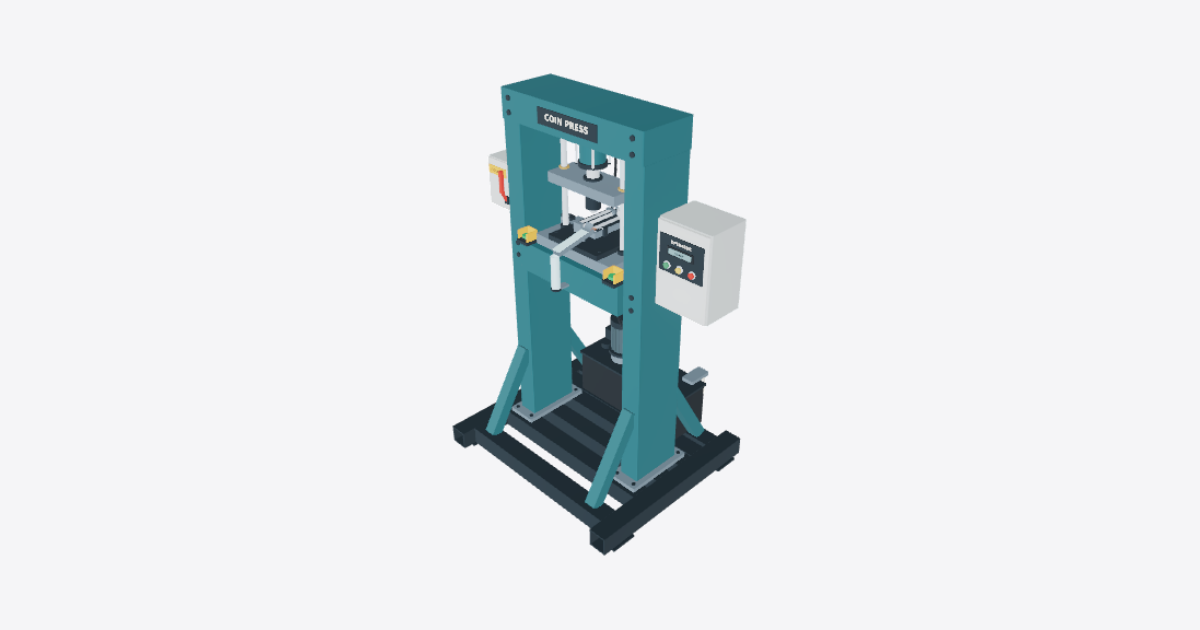
Start with the preassembled press
Keep the press frame and skid, guided platen, bolster, hydraulic power pack, and electrical and operator controls together as one base unit. Before entering the tooling area, isolate and verify all energy sources, relieve stored pressure, and secure the ram against movement. Keep the tooling and feed path empty during assembly.
Position the receiver bracket
Position the receiver bracket below the front discharge outlet, with its outboard end supporting the receiver location.
Seat the tooling subplate
Seat the tooling subplate flat on the ground bolster and align the four modeled fastening locations.
Start the first subplate fastener
Start the highlighted hex-head fastener at the left-front seat. Leave it loose until all four are started.
Start the second subplate fastener
Start the highlighted hex-head fastener at the right-rear seat.
Start the third subplate fastener
Start the highlighted hex-head fastener at the left-rear seat.
Fit the fourth subplate fastener
Start the highlighted hex-head fastener at the right-front seat. Keep the subplate flat as the fasteners are secured to the approved specification.
Position the magazine support
Position the magazine support on the infeed side of the subplate, next to the feed tube location.
Position the collar lug
Position the collar lug on the inboard face of the magazine support so it reaches toward the feed axis.
Position the air-jet pillar
Position the air jet pillar alongside the die station on the subplate, with the nozzle location facing the coin path.
Position the die holder
Position the die holder square against the underside of the secured guided platen.
Fit the upper coining die
Seat the upper coining die in the holder with the working face toward the bolster. Do not move the ram to seat the die.
Seat the shuttle bed
Seat the ground shuttle bed on the tooling subplate with the anvil opening beneath the upper die.
Seat the recessed lower anvil
Seat the recessed lower anvil in the shuttle-bed opening. Check that the rim is flush with the bed and centered beneath the upper die without cycling the press.
Position the discharge chute saddle
Position the chute saddle beneath the discharge path so the pan will be supported as it leaves the die station.
Position the discharge pan
Position the discharge pan with its inlet at the die station and its outlet sloping toward the receiver.
Position the right discharge wall
Position the right chute side wall along the right edge of the discharge pan, viewed from the operator side.
Position the left discharge wall
Position the left chute side wall along the remaining edge of the discharge pan.
Position the discharge deflector hood
Position the curved steel deflector hood at the inlet to guide ejected coins down into the discharge pan.
Fit the discharge inspection lid
Fit the inspection lid over the side walls, leaving the outlet clear.
Position the stack receiver base
Position the stack receiver base on the receiver bracket beneath the chute outlet.
Fit the stacking magazine
Seat the empty stacking magazine on the receiver base with its opening below the discharge outlet.
Seat the left slideway strip
Seat the left slideway strip along the left edge of the shuttle bed, viewed from the operator side.
Seat the right slideway strip
Seat the right slideway strip parallel to the left strip on the opposite edge of the bed.
Position the open-fork shuttle
Position the open-fork shuttle between the slideway strips, with the fork toward the die station and the drive end toward the infeed.
Fit the left retainer lip
Position the left retainer lip over its slideway strip with the overhang facing inward above the shuttle edge.
Fit the right retainer lip
Position the right retainer lip above the remaining shuttle edge, with the overhang facing inward. Keep the running path unobstructed.
Position the ejection nozzle
Position the ejection nozzle at the air-jet pillar facing the discharge inlet. Leave the air supply isolated.
Position the feed-tube collar
Position the aluminum magazine collar against the collar lug, centered above the infeed location.
Fit the clear feed tube
Seat the empty clear polycarbonate feed tube through the magazine collar with its outlet aligned over the shuttle loading location.
Position the shuttle drive crossbar
Position the shuttle drive crossbar across the infeed end of the shuttle, extending toward the cylinder location.
Position the rod attachment lug
Position the rod attachment lug on the actuator end of the crossbar, in line with the piston rod.
Position the pneumatic actuator as a unit
Position the pneumatic actuator beside and parallel to the shuttle track, with the rod facing the drive crossbar. Keep the cylinder, end blocks, piston rod and ties assembled and the air supply isolated.
Position the floating coupler body
Position the floating coupler body on the exposed piston rod with its mating end toward the rod attachment lug.
Fit the coupler neck
Fit the coupler neck at the interface between the coupler body and lug. Keep the press and air supply isolated. Do not load coins or run the press as part of this assembly procedure.