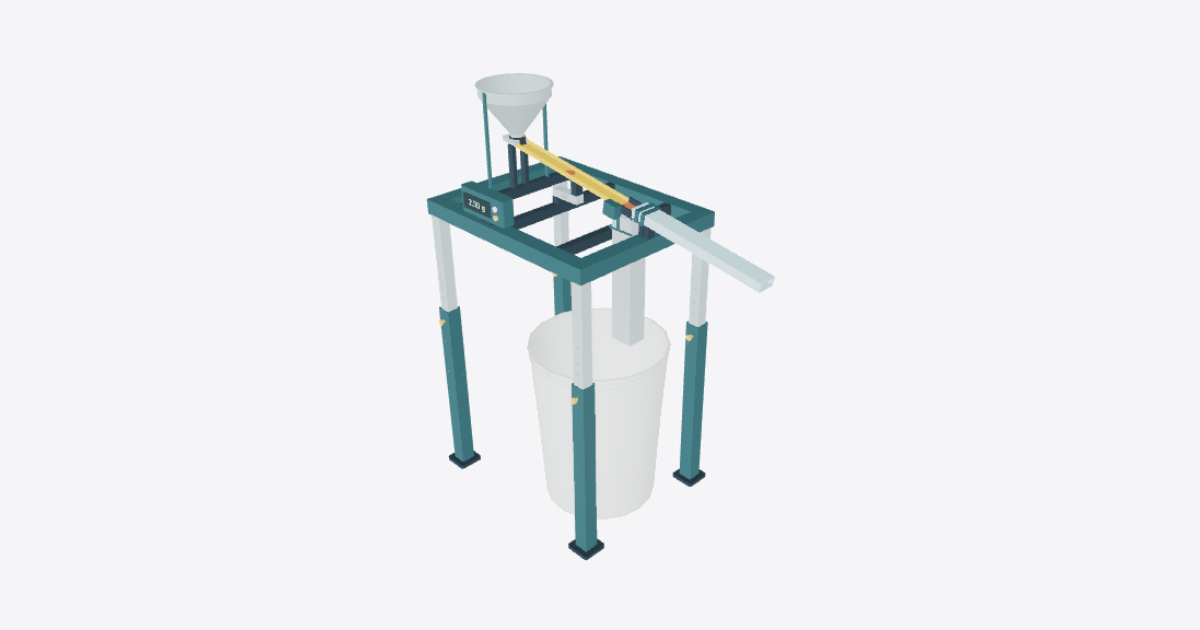
Build the Stage 2 electronic coin checkweigher from the
51 steps
Place the infeed floor pad on the console side
Set the floor pad flat at the infeed corner on the console side.
Place the opposite infeed floor pad
Set the floor pad flat at the other infeed corner, across from the first pad.
Place the discharge floor pad on the console side
Set the floor pad flat at the discharge corner on the console side.
Place the opposite discharge floor pad
Set the floor pad flat at the remaining discharge corner.
Fit the infeed outer sleeve on the console side
Center the outer sleeve upright on its floor pad with the pin access facing out. Support it until the frame can hold it upright.
Fit the opposite infeed outer sleeve
Center the outer sleeve upright on its infeed floor pad with the pin access facing out. Support it until the frame can hold it upright.
Fit the discharge outer sleeve on the console side
Center the outer sleeve upright on its discharge floor pad with the pin access facing out. Support it until the frame can hold it upright.
Fit the opposite discharge outer sleeve
Center the outer sleeve upright on the remaining floor pad with the pin access facing out. Support it until the frame can hold it upright.
Insert the infeed inner tube on the console side
Lower the perforated inner tube into the sleeve. Align the hole row with the sleeve's pin opening and support the tube at the selected height.
Fit the infeed locking pin on the console side
Seat the locking pin through the aligned opening to retain the inner tube. Keep the leg supported until the pin is seated.
Insert the opposite infeed inner tube
Lower the perforated inner tube into its sleeve. Align the matching height hole with the sleeve opening and support the tube.
Fit the opposite infeed locking pin
Seat the locking pin at the aligned hole. Check that it retains the inner tube before releasing the tube.
Insert the discharge inner tube on the console side
Lower the perforated inner tube into the discharge sleeve. Align the matching height hole with the sleeve opening and support the tube.
Fit the discharge locking pin on the console side
Seat the locking pin at the aligned hole. Check that it retains the inner tube before releasing the tube.
Insert the opposite discharge inner tube
Lower the perforated inner tube into the remaining sleeve. Align the matching height hole with the sleeve opening and support the tube.
Fit the opposite discharge locking pin
Seat the locking pin at the aligned hole. Check that all four pins are seated and the tops of the inner tubes are level with one another.
Fit the console-side long rim rail
Position the long rim rail across the two inner tubes on the console side. Keep the rail and legs supported until the rim is secured.
Fit the opposite long rim rail
Position the long rim rail across the two opposite inner tubes, parallel to the console-side rail.
Fit the infeed end rim rail
Fit the end rim rail between the long rails at the funnel end. Align its top with both long rails.
Fit the discharge end rim rail
Fit the end rim rail between the long rails at the discharge end. Check that the rim is square and secure before loading the stand.
Fit the infeed equipment bearer
Position the equipment bearer across the long rails at the station nearest the infeed. Align its top with the rim.
Fit the weighing equipment bearer
Position the equipment bearer across the long rails at the middle station, beneath the load-cell pedestal location.
Fit the gate equipment bearer
Position the equipment bearer across the long rails at the station nearest the discharge, beneath the gate.
Fit the fixed-end pedestal
Seat the fixed-end pedestal centrally on the weighing bearer with its beam mounting face up.
Mount the load cell
Fit the strain-gauge weighing beam as a unit. Seat its fixed end on the pedestal and leave the discharge-facing live end clear of the frame.
Fit the live-end saddle
Seat the live-end saddle on the unsupported end of the beam, with its track seat facing up.
Fit the live weighing track
Seat the live weighing track on the saddle, sloping down from the infeed toward the gate. Check that the saddle is the track's only support.
Fit the servo-side gate bracket
Position the outboard gate bracket on the gate bearer on the console side of the coin path. Keep it clear of the live track.
Fit the opposite gate bracket
Position the outboard gate bracket across the coin path from the servo-side bracket. Align the two cheek mounting positions.
Fit the servo-side gate cheek
Fit the gate side cheek to the servo-side bracket with its spindle hole at the weighing-track end.
Fit the opposite gate cheek
Fit the gate side cheek to the opposite bracket. Align its spindle hole with the hole in the servo-side cheek.
Place the reject trapdoor
Hold the reject trapdoor between the cheeks in its closed position. Align the hinge bore with the cheek holes.
Insert the trapdoor spindle
Slide the trapdoor spindle through the aligned cheek holes and hinge bore. Check that the door pivots without binding or touching the weighing track.
Mount the rotary gate servo
Fit the rotary gate servo as one unit outside the servo-side cheek. Align its output with the spindle axis with the trapdoor closed.
Fit the vertical reject chute
Bring the reject chute up from below the rim. Position its inlet directly under the trapdoor and leave the trapdoor's swing clear.
Fit the gate-side tube saddle
Seat the tube saddle on the discharge end rail at the position closest to the gate. Face the support surface toward the tube.
Fit the downstream tube saddle
Seat the tube saddle at the downstream position on the discharge end rail. Align it with the gate-side saddle along the coin path.
Fit the gate-side outlet ferrule
Position the tube ferrule on the saddle nearest the gate. Align its rectangular opening with the downhill coin path.
Fit the downstream outlet ferrule
Position the tube ferrule on the downstream saddle. Align its opening with the first ferrule.
Seat the accepted-coin outlet tube
Guide the clear outlet tube through the ferrules from the discharge side. Align its inlet with the closed gate and its outlet downhill toward Machine 3. Stop if the tube binds.
Fit the infeed stay on the console side
Set the funnel rim stay upright on the infeed bearer, outboard of the coin path on the console side.
Fit the opposite infeed stay
Set the funnel rim stay upright on the other side of the infeed bearer. Align its top with the first stay.
Fit the console-side runway support
Place the runway support upright on the infeed bearer, inboard of the console-side funnel stay.
Fit the opposite runway support
Place the runway support across the coin path from the first support so both can seat the discharge runway.
Seat the funnel discharge runway
Seat the funnel discharge runway on its supports with the exit aligned to the live weighing track. Leave a gap so the runway cannot carry any of the track's load.
Position the spout clamp band
Hold the spout clamp band centered over the runway at the funnel spout location. Orient the flap mounting side toward the weighing track.
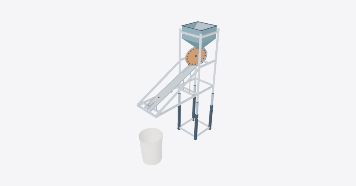
Seat the gravity funnel
Lower the gravity funnel between the rim stays and guide the spout into the clamp band above the runway. Seat the rim without shifting the runway.
Fit the rubber metering flap
Fit the rubber metering flap on the downstream side of the spout clamp band. Let the free edge hang into the coin path without contacting the weighing track.
Fit the console foot
Position the console foot on the console-side long rim rail, between the infeed and weighing stations.
Mount the digital scale indicator
Seat the digital scale indicator on the console foot as one unit. Face the display and both keys outward so they are accessible from beside the stand.
Place the reject pail
Slide the reject pail in from the console side between the legs, then shift it toward the discharge end until the chute outlet is over the open mouth. Check that the pail can be removed without disturbing the chute.