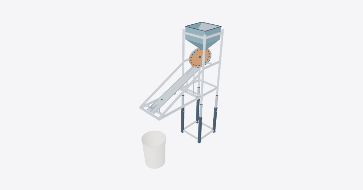
Create a step-by-step assembly procedure building from the
106 steps
Prepare the assembly area
Clear a level assembly surface and lay out the parts. Keep the tower supported as it is built and keep the motor disconnected throughout assembly.
Position foot pad 1
Place foot pad 1 at the first ramp-side corner, flat on the assembly surface.
Position foot pad 2
Place foot pad 2 at the rear corner directly behind pad 1.
Position foot pad 3
Place foot pad 3 at the other ramp-side corner, across from pad 1.
Position foot pad 4
Place foot pad 4 behind pad 3 to complete the base footprint.
Seat steel sleeve 1
Seat steel sleeve 1 upright on pad 1 with the pin opening oriented as shown.
Seat steel sleeve 2
Seat steel sleeve 2 upright on pad 2 with the pin opening oriented as shown.
Seat steel sleeve 3
Seat steel sleeve 3 upright on pad 3 with the pin opening oriented as shown.
Seat steel sleeve 4
Seat steel sleeve 4 upright on pad 4 with the pin opening oriented as shown.
Fit the first base side tie
Fit the first base side tie between sleeves 1 and 2 near the feet.
Fit the second base side tie
Fit the second base side tie between sleeves 3 and 4 near the feet.
Fit the ramp-side base cross tie
Fit the ramp-side base cross tie between sleeves 1 and 3.
Fit the rear base cross tie
Fit the rear base cross tie between sleeves 2 and 4. Check that the base sits flat and square before building upward.
Insert indexed tube 1
Lower indexed tube 1 into sleeve 1 and hold its selected index hole in line with the sleeve opening.
Insert locking pin 1
Slide locking pin 1 through the aligned holes until the keeper opening is exposed.
Fit keeper 1
Fit keeper 1 through the exposed hole in locking pin 1. Check that the pin cannot back out.
Insert indexed tube 2
Lower indexed tube 2 into sleeve 2 and hold its index hole in line with the sleeve opening at the matching height.
Insert locking pin 2
Slide locking pin 2 through the aligned holes in leg 2 until the keeper opening is exposed.
Fit keeper 2
Fit keeper 2 through the exposed hole in locking pin 2. Check that the pin cannot back out.
Insert indexed tube 3
Lower indexed tube 3 into sleeve 3 and hold its index hole in line with the sleeve opening at the matching height.
Insert locking pin 3
Slide locking pin 3 through the aligned holes in leg 3 until the keeper opening is exposed.
Fit keeper 3
Fit keeper 3 through the exposed hole in locking pin 3. Check that the pin cannot back out.
Insert indexed tube 4
Lower indexed tube 4 into sleeve 4 and hold its index hole in line with the sleeve opening at the matching height.
Insert locking pin 4
Slide locking pin 4 through the aligned holes in leg 4 until the keeper opening is exposed.
Fit keeper 4
Fit keeper 4 through the exposed hole in locking pin 4. Check that all four leg tops are level before adding uprights.
Place upright adapter plate 1
Center upright adapter plate 1 on top of indexed tube 1.
Place upright adapter plate 2
Center upright adapter plate 2 on top of indexed tube 2.
Place upright adapter plate 3
Center upright adapter plate 3 on top of indexed tube 3.
Place upright adapter plate 4
Center upright adapter plate 4 on top of indexed tube 4.
Set tower upright 1
Set tower upright 1 squarely on adapter plate 1 and support it vertically.
Set tower upright 2
Set tower upright 2 squarely on adapter plate 2 and support it vertically.
Set tower upright 3
Set tower upright 3 squarely on adapter plate 3 and support it vertically.
Set tower upright 4
Set tower upright 4 squarely on adapter plate 4 and support it vertically.
Fit the first lower tower side tie
Fit the first lower tower side tie between uprights 1 and 2 at the lower frame level.
Fit the second lower tower side tie
Fit the second lower tower side tie between uprights 3 and 4 at the same level.
Fit the lower ramp-side tower cross tie
Fit the lower ramp-side tower cross tie between uprights 1 and 3.
Fit the lower rear tower cross tie
Fit the lower rear tower cross tie between uprights 2 and 4.
Fit the first upper tower side tie
Fit the first upper tower side tie between uprights 1 and 2 at the hopper support level.
Fit the second upper tower side tie
Fit the second upper tower side tie between uprights 3 and 4 at the same level.
Fit the upper ramp-side tower cross tie
Fit the upper ramp-side tower cross tie between uprights 1 and 3 at the hopper support level.
Fit the upper rear tower cross tie
Fit the upper rear tower cross tie between uprights 2 and 4. Check that the tower is square and stable before adding the cantilever.
Fit the first cantilever side rail
Position the first cantilever side rail at the lower frame level on upright 1. Support its free end.
Fit the second cantilever side rail
Position the second cantilever side rail on upright 3, parallel with the first rail. Support its free end.
Fit the ramp end tie
Fit the ramp end tie across the free ends of the two cantilever rails.
Fit the first upper diagonal stay
Fit the first upper diagonal stay from upright 1 down to the outboard end of the first cantilever rail.
Fit the second upper diagonal stay
Fit the second upper diagonal stay from upright 3 down to the outboard end of the second cantilever rail.
Fit the inboard slide mounting tie
Span the cantilever rails with the inboard slide mounting tie near the tower.
Fit the first inboard tie end shoe
Seat the first inboard tie end shoe at the highlighted end of the inboard slide mounting tie.
Fit the second inboard tie end shoe
Seat the second inboard tie end shoe at the opposite end of the inboard slide mounting tie.
Fit the outboard slide mounting tie
Span the cantilever rails with the outboard slide mounting tie near the outlet.
Fit the first outboard tie end shoe
Seat the first outboard tie end shoe at the highlighted end of the outboard slide mounting tie.
Fit the second outboard tie end shoe
Seat the second outboard tie end shoe at the opposite end of the outboard slide mounting tie.
Fit the first tall slide standoff
Seat the first tall slide standoff on the inboard mounting tie at the highlighted sorting-plate support point.
Fit the second tall slide standoff
Seat the second tall slide standoff at the other sorting-plate support point on the inboard tie.
Fit the first short slide standoff
Seat the first short slide standoff on the outboard mounting tie at the highlighted support point.
Fit the second short slide standoff
Seat the second short slide standoff at the other support point on the outboard tie.
Seat the aluminum sorting plate
Seat the aluminum sorting plate on the four standoffs with the inlet high at the tower and the outlet low at the ramp end.
Fit the first outside edge rail
Fit the first outside edge rail along the highlighted long edge of the sorting plate.
Fit the second outside edge rail
Fit the second outside edge rail along the opposite long edge of the sorting plate.
Fit the entry guide
Fit the entry guide at the upper end of the sorting plate and align it with the incoming coin path shown.
Position the metering blade
Position the metering blade across the entry path at the highlighted location. Keep it aligned for the clamps.
Fit the first gate clamp
Seat the first gate clamp over the highlighted end of the metering blade.
Fit the second gate clamp
Seat the second gate clamp over the opposite end of the metering blade. Check that the blade stays aligned across the entry path.
Place N52 tile 01
Place N52 tile 01 at the highlighted position beneath the sorting plate. Keep fingers clear of the gap as the tile approaches.
Place N52 tile 02
Place N52 tile 02 at its highlighted position in the diagonal array beneath the plate. Keep fingers clear of adjacent tiles.
Place N52 tile 03
Place N52 tile 03 at its highlighted position in the diagonal array beneath the plate.
Place N52 tile 04
Place N52 tile 04 at its highlighted position in the diagonal array beneath the plate.
Place N52 tile 05
Place N52 tile 05 at its highlighted position in the diagonal array beneath the plate.
Place N52 tile 06
Place N52 tile 06 at its highlighted position in the diagonal array beneath the plate.
Place N52 tile 07
Place N52 tile 07 at its highlighted position in the diagonal array beneath the plate.
Place N52 tile 08
Place N52 tile 08 at its highlighted position in the diagonal array beneath the plate.
Place N52 tile 09
Place N52 tile 09 at its highlighted position in the diagonal array beneath the plate.
Place N52 tile 10
Place N52 tile 10 at its highlighted position in the diagonal array beneath the plate.
Place N52 tile 11
Place N52 tile 11 at its highlighted position in the diagonal array beneath the plate.
Place N52 tile 12
Place N52 tile 12 at its highlighted position in the diagonal array beneath the plate.
Place N52 tile 13
Place N52 tile 13 at its highlighted position in the diagonal array beneath the plate.
Place N52 tile 14
Place N52 tile 14 at its highlighted position beneath the plate. Check that all 14 tiles follow the shown diagonal layout.
Fit the downstream lane separator
Fit the downstream lane separator at the outlet end of the sorting plate, aligned with the two discharge paths.
Position the pivoting flipper
Lay the pivoting aluminum flipper on the sorting plate. Align its downstream pivot hole with the hole in the plate.
Fit the captured pivot rivet
Fit the captured pivot rivet at the aligned pivot holes in the plate and flipper. Check that the flipper can pivot without binding.
Fit the arcuate clamp bridge
Seat the arcuate clamp bridge across the edge rails and align its slot with the flipper adjustment point.
Install the M4 locking thumbscrew
Start the M4 locking thumbscrew by hand through the bridge slot into the flipper. Hold the flipper at the shown position and snug the thumbscrew by hand.
Fit the first zinc outlet cheek
Fit the first zinc outlet centering cheek along the highlighted side of the zinc lane.
Fit the second zinc outlet cheek
Fit the second zinc outlet centering cheek on the opposite side of the zinc lane, converging toward the drop opening.
Fit the zinc outlet backstop
Fit the zinc outlet backstop at the end of the zinc lane so coins are directed toward the drop opening.
Align the zinc discharge funnel
Position the zinc discharge funnel directly under the zinc drop opening with its outlet vertical.
Fit the first hopper mounting flange
Fit the first hopper mounting flange along the upper side tie between uprights 1 and 2.
Fit the second hopper mounting flange
Fit the second hopper mounting flange on the opposite upper side tie, parallel with the first flange.
Seat the hopper body
Lower the hopper body onto its mounting flanges from above. Orient the offset throat toward the rotary carrier location.
Fit the hopper load-relief shelf
Fit the load-relief shelf inside the hopper at the shown angle above the throat. Keep the delivery opening clear.
Fit the ramp-side rolled hopper lip
Seat the ramp-side rolled hopper lip along the top edge nearest the ramp.
Fit the rear rolled hopper lip
Seat the rear rolled hopper lip along the top edge opposite the ramp.
Fit the first side rolled hopper lip
Seat the first side rolled hopper lip along the top edge above the first mounting flange, between the front and rear lips.
Fit the second side rolled hopper lip
Seat the second side rolled hopper lip along the remaining top edge. Check that the lips meet at the corners without projecting into the feed opening.
Fit the first drive bearer
Fit the first drive bearer between uprights 1 and 2 below the hopper, at the highlighted drive support level.
Fit the second drive bearer
Fit the second drive bearer between uprights 3 and 4, level with the first drive bearer.
Fit the drive support bridge
Fit the drive support bridge across the bearers at the highlighted position beneath the hopper throat.
Position the worm reducer
Position the right-angle worm reducer on the drive support, with its output facing the carrier and its motor input facing the side shown.
Fit the reducer mounting spacer
Seat the reducer mounting spacer against the reducer output face, with its bore aligned to the output axis.
Mount the complete motor
Mount the complete 12 V motor at the reducer input. Keep the motor housing and the end cap together, and leave power disconnected.
Seat the output spindle
Seat the output spindle on the reducer output axis through the spacer, with the carrier end projecting toward the ramp side.
Fit the continuous carrier backplate
Center the continuous carrier backplate on the output axis behind the pocketed carrier location.
Fit the pocketed rotary carrier
Center the pocketed rotary carrier on the output axis with the backplate behind the coin pockets.
Fit the drive hub
Seat the drive hub at the center of the carrier, aligned with the output spindle.
Align the peripheral discharge guide
Fit the peripheral discharge guide around the carrier with its opening aligned to the ramp inlet. Check that the guide does not touch the carrier and that the throat feeds into the pocket path.
Position the collection pail
Place the collection pail on the floor directly below the zinc funnel. Check that the funnel outlet is over the open mouth and that the pail sits flat.