TwinWorks
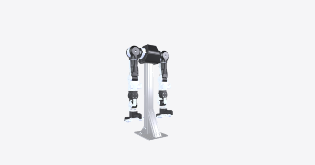
reBot DevArm B601 robot arm – 3D model preview

reBot DevArm B601 robot arm

Téa · Robotics · 3D model · Updated 13 Nov 2026

Open in 3D

  • Procedures4shared publicly
  • Views0all time
  • Rating–No ratings yet
  • Likes0from the Community

0 comments

Procedures

1. Base and joint 1

Assembly · 11 steps · No ratings yet

Notice: Tighten screws to 3 to 6 kgf·cm to avoid stripping the threads.

11 steps
  1. Prepare the base components and tightening method

    Lay out the base plate and the base components on a stable work surface. Keep the base open during motor installation and harness connection.

    For every screw in this procedure, tighten to 3 to 6 kgf·cm. Start the threads by hand and stop if a screw binds. The shipped screws already carry threadlocker; do not add more. Match the screw names below to the highlighted placements.

    reBot DevArm B601-DM by Seeed Studio (© 2026 Seeed Studio Co., Ltd.). Hardware licence: CERN-OHL-W-2.0.

  2. Configure motor 1 before fitting it

    Before installing the DM-J4340P motor (motor 1), the DM4340P motor at the base, use DM Tools to set its CAN ID to 0x01 and master ID to 0x11. Read the settings back and verify both values.

    Disconnect the configuration supply before mechanical assembly. Keep this motor identified as motor 1.

  3. Position the base link with the base open

    Position base link with its upper bearing seat and motor opening oriented as shown. Leave base plate separate so the motor can be introduced from below and its connectors remain accessible.

  4. Fit the reinforcement and motor locating pins

    Seat motor 1 bearing mount on the upper interface of the base housing. Match the hole pattern and recesses to the orientation shown.

    Fit PIN-D3L8 and second locating pin in the two motor locating holes. Keep the pins square and leave the motor-side locating ends available. Do not use screws to force misaligned mating parts together.

  5. Fit the DM-J4340P motor (motor 1)

    Verify that the DM-J4340P motor (motor 1) is already configured as CAN ID 0x01, master ID 0x11. Introduce the motor through the open underside of the base.

    Align the motor with the locating pins and reinforcement, keeping its connectors accessible through the housing openings. Seat the mating faces without trapping wires. Support the motor until its mounting screws are installed.

  6. Secure motor 1 with five M3 x 8 mm low-head screws

    Install the five M3 x 8 mm low-head screws at the highlighted motor-to-reinforcement mounting positions. Use this exact screw type from the model metadata.

    Start all five screws by hand, then tighten progressively and evenly to 3 to 6 kgf·cm. Check that the motor and reinforcement sit flush and that no cable is caught at the interface.

  7. Seat the thrust bearing and the ball bearing

    Fit AXK5578 thrust bearing, the thrust bearing, into the outer annular seat at the top of the base. Keep its supplied bearing components together and seated flat in the arrangement shown.

    Fit 6707ZZ ball bearing into the central radial-bearing seat. Apply seating force only to the ring entering its seat, not through the rolling elements. Both bearings must be square and fully seated before fitting the output plate.

  8. Fit the joint 1 output plate

    Lower joint 1 output plate onto the motor output and bearing stack. Align its mounting holes and yaw-stop feature with the orientation shown. Seat the plate without displacing either bearing.

    Keep the output plate seated and supported. Its final clamping with the shoulder support is completed in the next procedure; do not install the shoulder components here.

  9. Connect the motor 1-to-motor 2 harness before closure

    With the supply disconnected and the base still open, connect the motor 1-to-motor 2 harness to the DM-J4340P motor (motor 1) and to motor 2. Motor 2 remains unmounted for the next procedure.

    Seat the connectors fully. Route the harness through the housing openings, clear of the bearings, rotating output plate and base-plate mating surfaces. Leave the motor 2 end accessible and free from tension. Do not close the base until this connection is complete.

  10. Close the base with the base plate and M4 x 75 mm screws

    Support the base and its seated output plate while bringing base plate into position beneath base link. Keep the connected harness outside the mating surfaces.

    Install the four M4 x 75 mm long screws at the highlighted underside positions. Start all four by hand, then tighten evenly to 3 to 6 kgf·cm. Check that the base plate is flush and the harness remains unpinched.

  11. Check the base and leave the output ready for the shoulder

    Check that the DM-J4340P motor (motor 1) is secured, both bearings remain seated, the base plate is flush, and the connected harness is clear of the moving interface.

    Keep joint 1 output plate seated and supported, with its shoulder mounting holes accessible. Retain the six KM3-16 screws for the subsequent shoulder-support installation. Do not energize the motor or transport the assembly with the output plate unsecured.

    Stop here. Fit the shoulder, arm, wrist and gripper in later procedures.
2. Shoulder and upper arm (joints 2 and 3)

Assembly · 14 steps · No ratings yet

14 steps
  1. Start from the finished base

    Start with the base closed and joint 1 output plate ready. Keep the arm supported and the motor supply disconnected during mechanical assembly.

    Assemble only the shoulder and arm for joints 2 and 3 of the reBot B601-DM follower arm. Leave motor 4 and the wrist for the next procedure. Tighten the screws fitted in this procedure to 3 to 6 kgf·cm.

  2. Fit the shoulder bracket and upper-arm limit

    Fit the upper-arm limit and the silicone pad to the shoulder bracket in the orientation shown, before access is closed. Secure the limit with the two KA3-12 screws shown.

    Locate the bracket on the ready joint 1 output plate using the first locating pin, the second locating pin and the third locating pin. Fit the six KM3-16 screws shown. Seat the bracket evenly and tighten the screws to 3 to 6 kgf·cm.

  3. Fit the shoulder bearing and shoulder flange

    Seat the shoulder bearing and the shoulder flange in the shoulder bracket as shown. Keep the bearing square and apply seating force only to the race being fitted. Do not pull a misaligned bearing into place with the screws.

    Fit the six KM3-12 screws shown. Tighten evenly to 3 to 6 kgf·cm. Check that the bearing remains seated without binding.

  4. Set the IDs of motors 2 and 3 before fitting

    Set and verify each motor's ID before it is fitted. Configure the two DM4340P motors separately:

    • Motor 2, shown as the shoulder motor at the shoulder: CAN ID 0x02, master 0x12.
    • Motor 3, shown as the elbow motor at the far end of the upper arm: CAN ID 0x03, master 0x13.

    Identify the configured motors so they cannot be interchanged. Disconnect the motor supply before continuing the mechanical assembly.

  5. Position the rear upper-arm plate and motor back spacers

    Support the rear upper-arm plate in its shown orientation. Position the motor 2 back spacer at the shoulder end for motor 2 and the motor 3 back spacer at the far end for motor 3.

    Align the holes and keep both spacers seated flat. Keep the opposite plate off so the motor mountings remain accessible.

  6. Fit motor 2 at the shoulder

    Before fitting the shoulder motor, verify that motor 2 is set to CAN ID 0x02 and master 0x12. With the supply disconnected, seat the motor against its back spacer in the orientation shown.

    Fit the first locating pin, the second locating pin and the third locating pin at their shown locating positions. Fit the six KM3-7 screws shown. Tighten evenly to 3 to 6 kgf·cm. Keep the motor leads clear of mating faces.

  7. Fit motor 3 at the elbow end of the upper arm

    Before fitting the elbow motor, verify that motor 3 is set to CAN ID 0x03 and master 0x13. With the supply disconnected, seat the motor against its back spacer at the far end of the upper arm.

    Fit the first locating pin, the second locating pin and the third locating pin at their shown locating positions. Fit the six KM3-7 screws shown. Tighten evenly to 3 to 6 kgf·cm. Keep the leads accessible and clear of the joint.

  8. Position the upper-arm fillers and captured cover

    Position the left upper-arm filler, the middle upper-arm filler and the right upper-arm filler between the upper-arm plates in their shown orientations. Position the lower arm cover before closing the opposite plate. Keep the motor leads out of the locating faces and cover edges.

    Start the KA3-12 screws shown at the filler positions without forcing the printed parts. Keep the parts aligned for the next step; complete tightening only after the opposite plate is seated.

  9. Close and secure the upper-arm plates

    Fit the front upper-arm plate opposite the installed plate, capturing the fillers and cover without trapping the motor leads. Align both motor mounting patterns before tightening.

    Fit the remaining KM3-7 screws shown. Fit the KM3-9 screws at their shown plate positions.

    Tighten these screws and the filler screws evenly to 3 to 6 kgf·cm. Check that the plates are seated and the printed parts are not pinched or distorted.

  10. Fit the motor 2 front spacer and secure the shoulder output

    Fit the motor 2 front spacer at the shoulder motor output in the orientation shown. Keep the arm supported while aligning the spacer and output mounting holes.

    Fit the six KM3-12 screws shown. Tighten evenly to 3 to 6 kgf·cm. Check that the spacer is flat and the shoulder mounting is secure.

  11. Fit the motor 3 bearing, flange and front spacer

    At the motor 3 end, seat the elbow bearing and the elbow flange on the rear support side in the orientation shown. Keep the bearing square and apply seating force only to the race being fitted.

    Fit the motor 3 front spacer on the motor output side. Check the rear stack, including the previously fitted back spacer, is seated and the front spacer lies flat. Keep both sides supported for the connecting links.

  12. Fit the upper-lower arm connecting links

    Fit the left connecting link on the motor 3 output side against the front spacer. Fit the right connecting link on the rear bearing and flange side. Match the handed orientations shown; do not exchange the links.

    Secure the output-side mounting with the six KM3-16 screws shown. Secure the rear-side mounting with the six KM3-9 screws shown. Tighten evenly to 3 to 6 kgf·cm.

    Leave the remaining link attachment holes available for the next arm assembly. Do not fit motor 4.

  13. Position the upper cover and check cable clearance

    Position the upper arm cover in its shown location. Keep its edges and the previously fitted cover clear of the motor leads and moving interfaces. Do not force the cover against unsupported edges or use it to align the metal parts.

    Check the seated covers and fillers for trapped leads, gaps caused by misalignment, and distortion. Leave motor 4 and the wrist uninstalled.

  14. Inspect joints 2 and 3

    Support the completed shoulder and upper arm. Check that both motor mountings, both upper-arm plates, the front and rear spacer stacks, the bearing seats and the connecting links are seated and secure. Confirm that the screws fitted in this procedure were tightened to 3 to 6 kgf·cm.

    Confirm the recorded motor assignments: motor 2, CAN ID 0x02 / master 0x12; motor 3, CAN ID 0x03 / master 0x13. Check that the leads remain clear of mating faces, covers and joint motion.

    Check the upper-arm limit and silicone pad are secure. Keep the assembly supported and the motor supply disconnected for handoff. Stop here, before motor 4 and the wrist.

3. Forearm and wrist (joints 4 to 6)

Assembly · 14 steps · No ratings yet

Warning: Keep the motor supply disconnected during mechanical work

14 steps
  1. Start from the finished upper arm

    Start from guide 2 (Shoulder and upper arm), with the base, shoulder and upper arm assembled and motors 2 and 3 fitted. This is guide 3 of 4 for the reBot DevArm B601-DM follower arm: assemble the forearm and joints 4 to 6, stopping before the gripper.

    Disconnect the motor supply and support the upper arm against falling or rotating. Keep the supply disconnected throughout mechanical work. Power only the separate, unfitted motor being configured in the ID-setting steps, then disconnect it again before fitting.

    Sort each step's highlighted screws separately. For every screw fitted in this guide, start the thread by hand and tighten evenly to 3 to 6 kgf·cm. Do not use a screw to pull a misaligned bearing, pin or plate into place.

  2. Set motor 4 to ID 4 before fitting

    Keep motor 4 separate from the arm. With the arm's motor supply disconnected, connect and power only this unfitted motor for configuration. Set the ID with Seeed's Motorbridge tool (motorbridge.seeedstudio.com) or the Damiao debugging tool, following the reBot B601-DM Getting Started guide on the Seeed Studio wiki. Set its ID to 4, and read the ID back to verify it.

    Switch off and disconnect the configuration supply and leads. Mark the motor as ID 4 and keep it unpowered for fitting.

  3. Fit the left forearm plate and upper-arm connection

    Support the arm and bring the left forearm side plate to the upper-arm end in the orientation shown. Seat the left connection plate and the motor 3 output spacer against the existing motor 3 output, with all hole patterns aligned.

    Use the six highlighted long M3 screws through the connection plate and output spacer into motor 3. Start all six before tightening evenly to 3 to 6 kgf·cm. Keep supporting the forearm until its opposite side is fitted.

  4. Fit motor 4 to the left forearm plate

    With the supply disconnected, bring motor 4, already set to ID 4, into the open forearm end. Align its output face and connector orientation with the model.

    Seat the three 4 mm diameter, 7 mm long locating pins in the matching motor holes. Fasten the motor body to the left forearm plate with the six highlighted short M3 screws. Tighten evenly to 3 to 6 kgf·cm. Leave the opposite side open for the rear support.

  5. Fit the forearm centre and left filler

    Fit the centre forearm filler between the side-plate positions without trapping any motor leads. Fit the left forearm filler against the left plate.

    Use the four highlighted medium M3 screws through the left connection plate and forearm plate into the centre filler. Use the four highlighted countersunk M3 screws for the left filler and the two highlighted countersunk M3 screws at the left-side centre-filler positions. Seat all parts before tightening the screws to 3 to 6 kgf·cm.

  6. Close the forearm and fit its rear supports

    Fit the motor 4 rear spacer, rear support bearing and rear support flange concentrically at the wrist end. Seat the right forearm plate and right connection plate, engaging the upper-arm support flange in the existing upper-arm bearing. Fit the right forearm filler, forearm handle and forearm cover in their matching seats.

    • Use the six highlighted short M3 screws around the motor 4 rear spacer to secure it to the right plate. Use the four highlighted medium M3 screws at the motor rear-support positions.
    • Use the six highlighted medium M3 screws around the right upper-arm connection. Use the other four medium M3 screws through the right connection and forearm plate into the centre filler.
    • Use the highlighted countersunk M3 screws in the countersunk side-plate holes: two at the right centre-filler positions, four at the right filler, and the remaining matching positions around the upper-arm connections and handle.

    Seat the bearing and flanges without using screw force. Tighten screws evenly to 3 to 6 kgf·cm. Keep the motor supply disconnected.

  7. Set motor 5 to ID 5 before fitting

    Keep motor 5 separate from the arm. Leave the arm supply disconnected. Connect and power only this unfitted motor for configuration. Set the ID with Seeed's Motorbridge tool (motorbridge.seeedstudio.com) or the Damiao debugging tool, following the reBot B601-DM Getting Started guide on the Seeed Studio wiki. Set its ID to 5, and read the ID back.

    Switch off and disconnect the configuration supply and leads. Mark the motor as ID 5. Do not fit it while powered.

  8. Build the wrist yoke on motor 4

    Seat the motor 4 output spacer and left wrist side plate on motor 4's output. Fit the right wrist side plate to the rear support flange, then seat the wrist bridge bracket between the two plates in the orientation shown.

    • Use the six highlighted long M3 screws through the left wrist plate and spacer into motor 4's output.
    • Use the six highlighted medium M3 screws around the right wrist plate's rear-support circle.
    • Use the six highlighted short M3 screws to attach the bridge bracket to the wrist side plates, three on each side.

    Start every screw before tightening evenly to 3 to 6 kgf·cm. Keep the supply disconnected.

  9. Fit motor 5 to the wrist bridge

    With the supply disconnected, seat motor 5, already set to ID 5, in the wrist bridge bracket. Match the connector and output-face orientation shown.

    Fit the three 4 mm diameter, 7 mm long locating pins into their matching motor holes. Use the six highlighted short M3 screws through the bridge bracket into the motor body. Tighten evenly to 3 to 6 kgf·cm. Leave the cable restraint and cover off until the wiring is routed.

  10. Set motor 6 to ID 6 before fitting

    Keep motor 6 separate from the arm. Leave the arm supply disconnected. Connect and power only this unfitted motor for configuration. Set the ID with Seeed's Motorbridge tool (motorbridge.seeedstudio.com) or the Damiao debugging tool, following the reBot B601-DM Getting Started guide on the Seeed Studio wiki. Set its ID to 6 and read the ID back.

    Switch off and disconnect the configuration supply and leads. Mark the motor as ID 6 and keep it unpowered for mechanical assembly.

  11. Fit the wrist roll carrier to motor 5

    Place the motor 5 output spacer on the output face, then seat the wrist roll carrier against it in the orientation shown. Keep the opening for motor 6 clear.

    Use the six highlighted M3 screws through the carrier and spacer into motor 5's output. Start all six before tightening evenly to 3 to 6 kgf·cm. Keep the motor supply disconnected.

  12. Seat motor 6 in the wrist roll carrier

    With the supply disconnected, insert motor 6, already set to ID 6, into the wrist roll carrier from the open tool end. Match the motor connector and mounting-hole orientation shown. Do not fit the gripper connectors or gripper motor.

    Keep the motor supported in its seat. Its two body-retaining screws also retain the inner cable-restraint half and are fitted with that restraint in the next step.

  13. Route leads and fit restraints, stop and cover

    Keep the supply disconnected and motor 6 supported. Route the motor leads through the forearm and wrist restraint channels, clear of screw tips, rotating faces and pinch points. Leave enough slack for joint movement without pulling on connectors.

    • Fit the motor 5 cable restraint with its four highlighted short M3 screws into motor 5.
    • Fit the inner wrist roll cable restraint. Install its two highlighted medium M3 screws through the restraint and carrier into motor 6 to retain the motor body. Fit the outer wrist roll cable restraint with the four highlighted countersunk M3 screws at the matching side positions, two per side.
    • Seat the soft stop pad on the wrist stop, then fasten the stop to the carrier with the two highlighted M3 screws.
    • Fit the motor 5 cover to the bridge bracket with its two highlighted M3 screws.

    Do not crush the leads under a restraint or cover. Tighten screws to 3 to 6 kgf·cm.

  14. Inspect joints 4 to 6

    With the motor supply still disconnected, inspect motor 4, motor 5 and motor 6 and their supports. Check that each motor is fully seated, all locating pins and spacers are seated, and the bearing supports are square.

    Check every screw fitted in this guide for the specified 3 to 6 kgf·cm tightening torque. Check that cable restraints hold the leads without crushing them, no wire passes through a screw hole or moving interface, and the wrist stop and soft pad are secure. Do not force an unpowered motor to test movement.

    Confirm the separately verified IDs are 4, 5 and 6. Leave the gripper connectors, gripper motor and gripper unfitted. Keep the motor supply disconnected for the handover to guide 4.

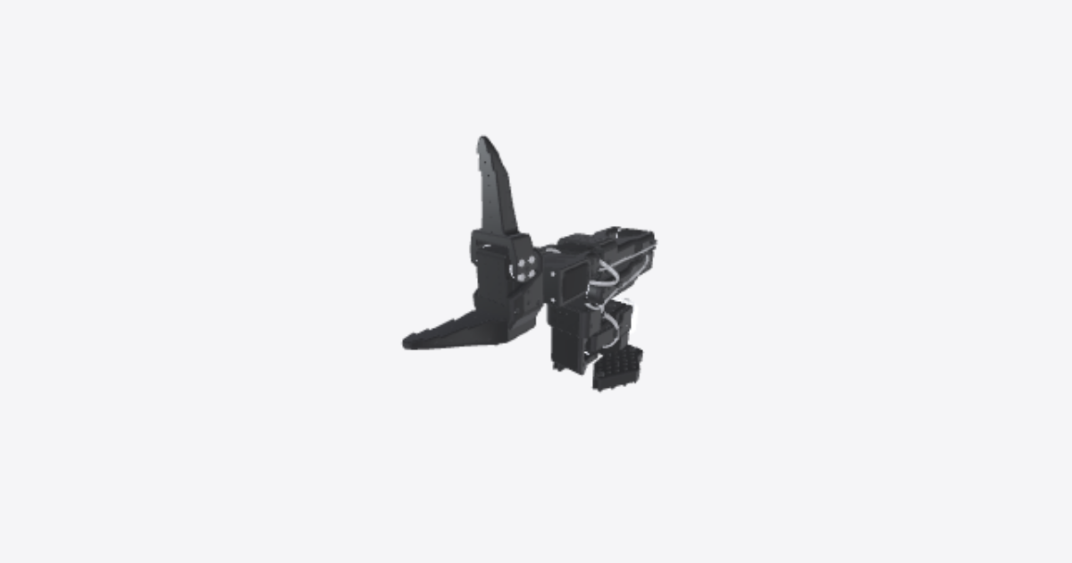
4. Gripper (motor 7)

Assembly · 12 steps · No ratings yet

Warning: Disconnect the motor supply before mechanical work and keep it disconnected during the hand check.

12 steps
  1. Set motor 7's ID before fitting it

    Start from the finished wrist from guide 3 (Forearm and wrist).

    Guide 4 of 4: gripper assembly. Start with the wrist finished and motor 6 fitted. Support the arm securely.

    Keep the gripper motor separate from the arm. Connect only this motor to the motor setup interface, apply setup power and set its ID to 7. Set the ID with DM Tools (Damiao) or Seeed's Motorbridge tool (motorbridge.seeedstudio.com), following the reBot B601-DM Getting Started guide on the Seeed Studio wiki. Read the ID back before fitting the motor. Switch off and disconnect the motor supply and setup leads.

    Keep the motor supply disconnected throughout the mechanical work and the final hand check. Tighten the screws fitted in this guide to 3 to 6 kgf·cm.

  2. Fit the wrist-to-gripper adapter rings

    Seat the small wrist adapter ring on motor 6's output face. Fit four M3 × 6 socket-head screws through its face holes into the motor output.

    Fit the large gripper mounting ring around the small ring. Align the radial holes and fit three M3 × 12 socket-head screws around the circumference to join the rings. Keep the cable passage clear. Tighten the screws to 3 to 6 kgf·cm.

  3. Fit motor 7 and the cable restraints

    Position the two cable-restraint halves around the gripper motor's mounting end, keeping the cable channels aligned and the leads clear of the mating faces. Seat the gripper motor against the mounting ring with its output facing the jaws.

    Fit four M3 × 12 socket-head screws through the mounting-ring and restraint stack into the motor's stationary mounting face. Fit four M3 × 12 countersunk screws in the recessed cable-restraint fixing holes. Tighten the screws evenly to 3 to 6 kgf·cm. Do not trap or crush a lead.

  4. Fit the gripper support plate

    Place the metal gripper support plate against the front stationary mounting face of motor 7, with the central opening concentric with the motor output. Align the four outer recessed fixing holes.

    Fit four M3 × 12 countersunk screws through these holes into the motor housing. Tighten diagonally to 3 to 6 kgf·cm, keeping the plate flat and clear of the rotating output.

  5. Fit the pinion drive hub

    Seat the pinion drive hub on motor 7's output through the support plate's central opening. Keep the projecting pinion shaft facing outward.

    Fit six M3 × 7 low-profile screws through the hub's bolt circle into the motor output. Start all six, then tighten evenly to 3 to 6 kgf·cm. Turn the hub gently by hand to ensure it does not rub the stationary plate.

  6. Fit the printed rail support

    Seat the printed rail support against the metal support plate, aligning the central clearance opening with the drive hub and the rail seat across the gripper.

    Fit six M3 × 7 low-profile screws through the six support fixing holes around the motor into the matching plate and housing holes. Tighten evenly to 3 to 6 kgf·cm. Keep the rail seat clean and the drive hub free to turn.

  7. Secure the linear guide rail

    Seat the linear guide rail in the printed support's straight locating channel. Align the six fixing positions along the rail.

    Fit six long M3 socket-head screws through the rail and printed support into the metal backing plate. Start all six before tightening progressively from the middle outward to 3 to 6 kgf·cm. Keep the rail straight and fully seated.

  8. Fit both slider blocks, jaw carriers and jaws

    Slide the two slider blocks onto opposite ends of the rail without forcing them. Keep each block supported so it cannot run off an end.

    Place the two metal jaw carriers on the slider blocks in mirror-image positions. Fit the two jaws with their gripping faces toward each other. Align each jaw's four fixing holes with its carrier and slider block.

    Fit eight M3 × 16 low-profile screws, four through each jaw and carrier into its slider block. Tighten evenly to 3 to 6 kgf·cm. Move each jaw gently along the rail to check that neither block binds.

  9. Attach the two opposed racks

    Fit the two toothed racks to the jaw carriers, one on each side of the drive hub, with both sets of teeth facing inward toward the pinion position. Keep the racks parallel to the rail.

    Fit four M3 × 6 socket-head screws, two through each rack's fixing holes into its jaw carrier. Tighten to 3 to 6 kgf·cm. Position the jaws equally about the gripper centre before fitting the pinion.

  10. Mesh and secure the drive pinion

    Slide the drive pinion onto the hub shaft while engaging both racks. Keep the jaws equally spaced about the centre and engage both racks at the same time. The teeth must mesh without forcing either rack sideways.

    Fit two M4 × 5 set screws into the radial threaded holes in the pinion boss. Tighten them against the hub shaft to 3 to 6 kgf·cm. Move the jaws gently together and apart to check that both racks remain engaged and the pinion does not rub the support.

  11. Complete the gripper cable routing

    With the motor supply still disconnected, route the gripper motor lead through the cable-restraint channels and connect its matching keyed connector to the arm harness. Do not force a connector.

    Keep the lead clear of the pinion, racks and jaw travel. Leave enough slack for wrist movement without pulling on a connector, and ensure no lead is pinched between the two cable-restraint halves. Check that the connectors are fully seated. Leave the motor supply disconnected.

  12. Check the finished arm and jaw movement by hand

    Keep the motor supply disconnected. Check that the gripper is secure on the wrist, all fitted screws are tightened to 3 to 6 kgf·cm, and the cables are clear of moving parts.

    Holding the two jaws from their outer surfaces, gently open and close them by hand through their usable travel. Keep fingers out of the gap between the jaws and away from the pinion and racks. Both jaws must move smoothly in opposite directions, remain centred and stay engaged with the pinion, with no sticking, scraping or cable interference. Do not force the jaws against an end stop.

    If movement is not free, stop and correct the alignment or obstruction with the supply disconnected, then repeat the hand check. Finish with the arm assembled and the jaws opening and closing freely by hand.

Related products

  • SO-101 robot arm

    Téa

    Robotics · 3D model · 8 procedures

    No ratings yet

    0 likes · 0 comments · 245 views

  • OpenArm v1.1 leader arm

    Téa

    Robotics · 3D model · 8 procedures

    No ratings yet

    1 like · 0 comments · 30 views

  • OpenAMR autonomous mobile robot

    Téa

    Robotics · 3D model · 3 procedures

    No ratings yet

    0 likes · 0 comments · 0 views

  • Koch v1.1 robot arm

    Téa

    Robotics · 3D model · 1 procedure

    No ratings yet

    0 likes · 0 comments · 0 views

  • OpenManipulator-X robot arm

    Téa

    Robotics · 3D model · 1 procedure

    No ratings yet

    0 likes · 0 comments · 1 view

  • LeKiwi mobile robot

    Téa

    Robotics · 3D model · 1 procedure

    No ratings yet

    0 likes · 0 comments · 13 views