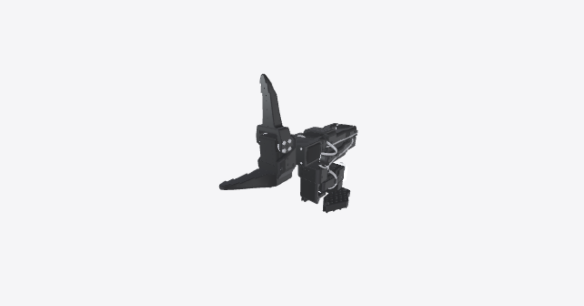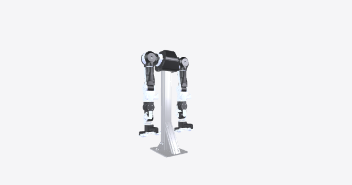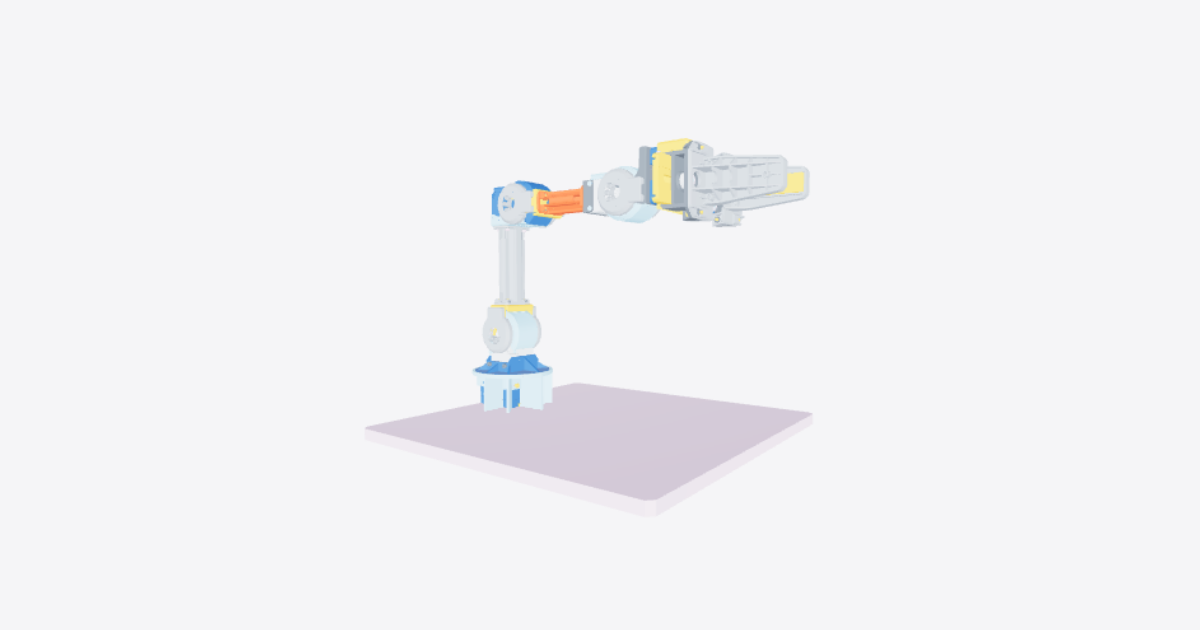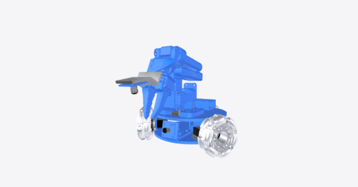
Full assembly
Tools
- 1.5 mm cross-head screwdriver
Notice: Use the follower's 12 V supply through its Waveshare board. The leader uses 5 V. Never swap the supplies.
Notice: Clamp the base securely to the table before use.
16 steps
Configure all six servo IDs before assembly
Connect one servo at a time to the Waveshare serial bus servo driver board and the computer. Replace YOUR_PORT with the connected port and run:
lerobot-setup-motors --robot.type=koch_follower --robot.port=YOUR_PORT
Complete and verify the ID assignment for each servo before installing it:
- Shoulder pan: XL430-W250-T, ID 1.
- Shoulder lift: XL430-W250-T, ID 2.
- Elbow flex: XL330-M288-T, ID 3.
- Wrist flex: XL330-M288-T, ID 4.
- Wrist roll: XL330-M288-T, ID 5.
- Gripper: XL330-M288-T, ID 6.
Disconnect power before changing the connected servo. Label each configured servo with its assigned ID. Keep power disconnected during mechanical assembly.
Koch v1.1 by Jess Moss and the Hugging Face team, based on Alexander Koch's low_cost_robot. Licence: Apache-2.0.
Position and clamp the base
Place base flat on the table in the orientation shown. Clamp the base securely before building upward. Keep its servo pocket and mounting positions accessible.
Throughout assembly, use M2 screws with a 1.5 mm cross-head screwdriver. Fit screws only at fastening positions shown in the model; leave unused holes empty. Keep servo housings assembled.
Install the shoulder-pan servo and base spacers
Verify that the shoulder-pan servo is assigned ID 1. Seat the servo in base, with its output facing shoulder rotation bracket's mounting position and its connectors accessible as shown.
Fit base spacer, base spacer, base spacer and base spacer at their four modelled base mounting positions. Secure the servo with M2 screws only at the fastening positions shown. Do not dismantle the servo or mistake its housing screws for additional mounting screws.
Fit the shoulder rotation bracket
Align shoulder rotation bracket with the ID 1 servo output in the orientation shown. Seat the interface without forcing the shaft and secure the modelled fastening positions with M2 screws. Leave the shoulder-lift servo seat accessible.
Install the shoulder-lift servo and its spacers
Verify that the shoulder-lift servo is assigned ID 2. Fit the servo onto shoulder rotation bracket with its shaft aligned to the shoulder-lift pivot shown.
Place shoulder-lift spacer, shoulder-lift spacer, shoulder-lift spacer and shoulder-lift spacer in their four modelled positions around this mounting interface. Secure the modelled fastening positions with M2 screws while the upper arm is still absent.
Fit the shoulder idler and upper arm
Bring upper arm onto the ID 2 shoulder-lift pivot in the orientation shown. Align the driven side with the servo output and fit shoulder idler at the opposite support pivot, matching the model.
Support the upper arm while seating both sides. Secure only the modelled fastening positions with M2 screws. Keep the pivot aligned and do not clamp the moving link against the servo housing.
Install the elbow-flex servo
Verify that the elbow-flex servo is assigned ID 3. Fit the intact servo at the upper end of upper arm, aligning its output with the elbow pivot shown. Keep the connector side accessible. Secure the modelled housing-mounting positions with M2 screws before fitting the forearm extension.
Attach the forearm extension and the elbow frame
Align forearm extension with the ID 3 elbow output and its opposite support, matching the modelled orientation. Fit elbow frame at the elbow's opposite-side interface as shown. Support the extension while securing the modelled fastening positions with M2 screws. Leave the distal wrist-servo mounting area accessible.
Install the wrist-flex servo
Verify that the wrist-flex servo is assigned ID 4. Seat the intact servo at the distal end of forearm extension with its shaft on the wrist-flex pivot shown. Secure the modelled mounting positions with M2 screws before closing the interface with the wrist bracket.
Fit the forearm and the wrist frame
Fit forearm around the ID 4 wrist-flex interface in the orientation shown. Align the driven side and fit wrist frame on the opposite side. Secure only the modelled fastening positions with M2 screws. Keep the wrist-roll servo seat unobstructed.
Install the wrist-roll servo
Verify that the wrist-roll servo is assigned ID 5. Fit the intact servo into forearm in the orientation shown, with its output directed toward the gripper mounting interface. Secure the modelled mounting positions with M2 screws, keeping its connectors accessible.
Attach the fixed jaw
Align fixed jaw with the ID 5 wrist-roll output as shown. Seat the interface without forcing the shaft and secure the modelled fastening positions with M2 screws. Keep the gripper-servo pocket and moving-jaw support accessible.
Install the gripper servo
Verify that the gripper servo is assigned ID 6. Seat the intact servo in fixed jaw with its output aligned to the moving-jaw pivot shown. Secure the modelled mounting positions with M2 screws before fitting the moving jaw. Leave the cable connectors accessible.
Fit the moving jaw and the gripper frame
Align moving jaw with the ID 6 servo output and the opposite jaw support. Match the jaw orientation shown and fit gripper frame at the opposite-side support interface. Secure the modelled fastening positions with M2 screws without clamping the moving jaw against fixed jaw.
Check that the jaws are aligned and that neither jaw traps a cable.
Connect the servo bus with power disconnected
Keep power disconnected. Connect the Waveshare serial bus servo driver board to the configured servos using the matching keyed bus connectors. Arrange the bus connections from shoulder pan ID 1 through shoulder lift ID 2, elbow flex ID 3, wrist flex ID 4, wrist roll ID 5 and gripper ID 6.
Route cables alongside the links, clear of shafts, support pivots and gripper jaws. Leave slack at each joint so movement cannot pull on a connector. Do not force plugs or connect the supply directly to an unidentified terminal.
Connect the follower's 12 V supply through its Waveshare board only after completing the connection checks. Keep the leader's 5 V supply separate.
Inspect the completed follower arm before use
Check the assembled arm from base to moving jaw against the model:
- The base is firmly clamped to the table.
- All links, the three support frame placements, shoulder idler and the eight XL430 spacer placements are seated as shown.
- The modelled fastening positions are secured with M2 screws; no unused hole has been filled merely because it is present.
- Servo IDs are 1 to 6 in order from shoulder pan to gripper.
- Connectors are seated, and cables cannot be pinched or pulled by the joints or jaws.
- The follower supply is 12 V through the Waveshare board, not the leader's 5 V supply.
Keep the work area clear before enabling motion. Begin with small controlled movements and stop if a joint binds, a cable tightens or a fastener moves.