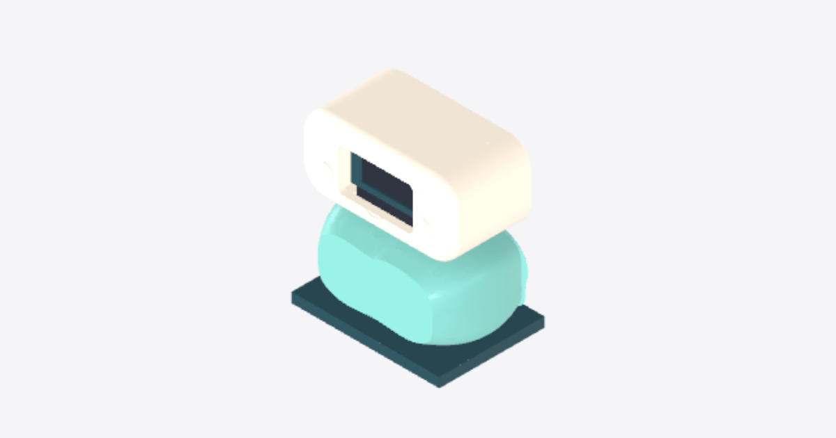
Desktop Robot Companion — Assembly
12 steps
Stage the head and body separately
Disconnect all power. Stage the Rounded head shell and Rounded torso shell separately. Leave the Head rear service cover and Torso rear service cover off. Keep fasteners with their parts and verify thread fit and engagement without bottoming out or damaging the print.
Fit the animated-eye OLED in the head
Dry-fit the Removable OLED bezel adapter and Waveshare 1.54-inch OLED in the Rounded head shell without forcing them. Center the active area and keep the connector reachable from the rear. Install the two OLED bezel screws. The display must sit flat without glass pressure or connector strain.
Mount the head-turn micro servo without its horn
With power off, align the head-turn servo with the rotation axis using the Rounded head shell and Fixed hollow neck sleeve as references. Secure it only to a mount that fits its tabs. Leave the display lead clear and the spline bare and accessible.
Mount the body-tilt micro servo without its horn
With power off, align the body-tilt servo at the tilt axis between the Rounded torso shell and Low fixed base. Support the torso upright. Use a mount that fits the tabs, check that the servo and lead clear the print, and leave the spline bare.
Mount the Raspberry Pi Zero 2 W
Use the Raspberry Pi Zero 2 W fit envelope to position the board inside the Torso rear service cover. Dry-fit with the real board and check plug access. Install the four Pi washers and four Pi screws. The board must sit flat without flexing, with hardware clear of components and traces.
Center both servos before attaching their horns
Support the shells and leave both horns off. Verify controller compatibility, pinout, polarity, and supply rating before powering up. Command both servos to their configured neutral, let them settle, and disconnect power without turning the splines. Align the Rounded head shell forward and the Rounded torso shell upright. Fit each horn at the nearest neutral spline with its matching retainer. Don’t use fasteners to force alignment.
Route and secure wiring at both joints
With power off and covers open, route the display lead through the Fixed hollow neck sleeve only if the plug passes freely and the lead clears the joint hardware. Use verified connectors. Leave a slack loop at each joint and secure fixed runs clear of moving parts, screw bosses, cover lips, and sharp edges. Leave slack to open the Torso rear service cover without pulling Pi plugs.
Join the head and body at neutral
Support the torso upright on the Low fixed base. Check that the Fixed hollow neck sleeve and Bonded neck retaining ring are secure and clear of wiring. Seat the Rounded head shell facing forward, keeping the servos centered and both cable loops free. Secure the joints only if they seat freely and the attachment points are clear.
Check joint clearances with power off
With power disconnected and covers off, support the assemblies. Check intended travel on each axis and both together at the Fixed hollow neck sleeve and between the Rounded torso shell and Low fixed base. Don’t back-drive the servos; disengage if needed and reconnect at neutral. Fix shell or horn contact and any cable rubbing, pinching, or tension before closing.
Close the head without trapping the display lead
Seat the Head rear service cover flush with the Rounded head shell. Keep the display lead and loop clear of the lip and bosses. Install the two head cover screws and leave their heads accessible.
Close the torso and preserve service access
Support the Pi and seat the Torso rear service cover flush with the Rounded torso shell without pinching wires or using screws to pull it shut. Fit the two torso cover screws. Check screw and plug access, then recheck joint gaps before powering up.
Run a low-speed motion and display test
On a stable surface, keep hands clear and power up at neutral. Check that the animated eyes on the Waveshare 1.54-inch OLED are upright and centered. At low speed, test small moves in both directions on each axis, then test both axes together within the checked range. Return to neutral before increasing travel. Cut power for binding, stalls, rubbing, cable pull, wrong direction, flicker, or resets. Finish at neutral and power down.