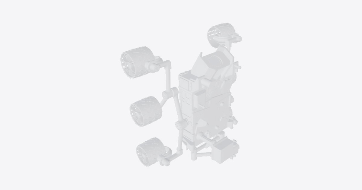
Assemble the Curiosity
22 steps
Prepare the body and sort the parts
Place the body on a clean, stable surface and support it while fitting the suspension. Sort the left and right suspension parts, six wheels and tires, instrument-arm parts, ChemCam and 17 pins. Keep the small pins together.
Fit the body mounting brackets
Fit mounting-bracket to the left body mounting point and mounting-bracket001 to the matching right point. Fit swivel-bracket at the instrument-arm mounting point. Match the mating profiles and seat each bracket without forcing it.
Fit the main upper suspension members
Fit upper-suspension-p1-left to the left mounting bracket and upper-suspension-p1-right to the right mounting bracket. Match the orientation shown and engage the mating pivots without forcing them.
Position the main lower suspension members
Position lower-suspension-p1-left at the left upper suspension pivot and lower-suspension-p1-right at the matching right pivot. Align the pin holes and support the members until the pins are fitted.
Insert the main suspension pivot pins
Insert 6mm-pin005 through the aligned left suspension pivot and 6mm-pin006 through the matching right pivot. Seat the pins in the positions shown. Check that both joints remain connected when you release their support.
Fit the suspension end members
Fit upper-suspension-p2-left and lower-suspension-p2-left to their matching left suspension members. Fit upper-suspension-p2-right and lower-suspension-p2-right to the matching right members. Match the mating profiles and orient the steering-bracket mounting holes as shown.
Position the four steering brackets
Position steering-bracket at upper-suspension-p2-left and steering-bracket001 at lower-suspension-p2-left. Position steering-bracket003 at upper-suspension-p2-right and steering-bracket002 at lower-suspension-p2-right. Align the pivot holes and support the brackets.
Insert the steering pivot pins
Insert 6mm-pin004 into the upper left steering pivot and 6mm-pin007 into the lower left steering pivot. Insert 6mm-pin011 into the upper right steering pivot and 6mm-pin009 into the lower right steering pivot. Seat each pin and gently check that its bracket can pivot without coming loose.
Position the six wheels
Position wheel and wheel003 on the left steering brackets, and wheel001 at the left center-wheel mounting point. Position wheel005 and wheel004 on the right steering brackets, and wheel002 at the right center-wheel mounting point. Align the wheel centers with the pin holes and support the wheels.
Insert the six wheel pins
Fit the wheel pins as follows:
- 6mm-pin001 through wheel; 6mm-pin002 through wheel001; 6mm-pin008 through wheel003.
- 6mm-pin012 through wheel005; 6mm-pin003 through wheel002; 6mm-pin010 through wheel004.
Seat each pin in the position shown. Turn each wheel gently to check that it rotates without binding or coming off its mounting point.
Fit the six tires
Fit tire to wheel, tire001 to wheel001, tire002 to wheel002, tire003 to wheel003, tire004 to wheel004 and tire005 to wheel005. Seat each tire evenly around its wheel without forcing or distorting it. Check that no tire rubs on the suspension.
Position the instrument-arm swivel
Position swivel in the body-mounted swivel bracket. Match the orientation shown and align the pivot holes. Support the swivel until its pin is fitted.
Secure the swivel pivot
Insert 6mm-pin014 through the aligned swivel-bracket and swivel holes. Seat the pin and check gently that the swivel is retained and can pivot without binding.
Position the upper instrument arm
Position upper-arm at the swivel joint in the orientation shown. Align the pivot holes and support the arm until its pin is fitted.
Secure the upper-arm pivot
Insert 6mm-pin through the aligned upper-arm and swivel holes. Seat the pin and check gently that the joint is retained and moves without binding.
Position the lower instrument arm
Position lower-arm at the free end of the upper arm. Match the orientation shown, align the pivot holes and support both members.
Secure the elbow pivot
Insert 6mm-pin016 through the aligned upper-arm and lower-arm holes. Seat the pin and check gently that the elbow is retained and moves without binding.
Position the MAHLI/APXS instrument
Position mahli-apxs at the free end of the lower arm. Match the orientation shown and align the pivot holes. Support the instrument until its pin is fitted.
Secure the instrument pivot
Insert 6mm-pin015 through the aligned lower-arm and instrument holes. Seat the pin and check gently that the instrument is retained without binding at its pivot.
Position ChemCam
Position chemcam on its body mounting point in the orientation shown. Align the pin holes and support the instrument until its pin is fitted.
Secure ChemCam
Insert 6mm-pin013 through the aligned ChemCam mounting holes. Seat the pin in the position shown and check gently that the instrument remains attached when its support is released.
Check the completed assembly
Support the body and remove the temporary support from beneath the suspension. Place the rover on a flat surface and check that all six tires contact it. Roll the rover gently and check that the wheels turn without rubbing or loosening. Gently articulate the suspension, steering brackets and instrument arm without forcing any joint. Check that all 17 pins remain seated, the body brackets are engaged and both instruments are retained.