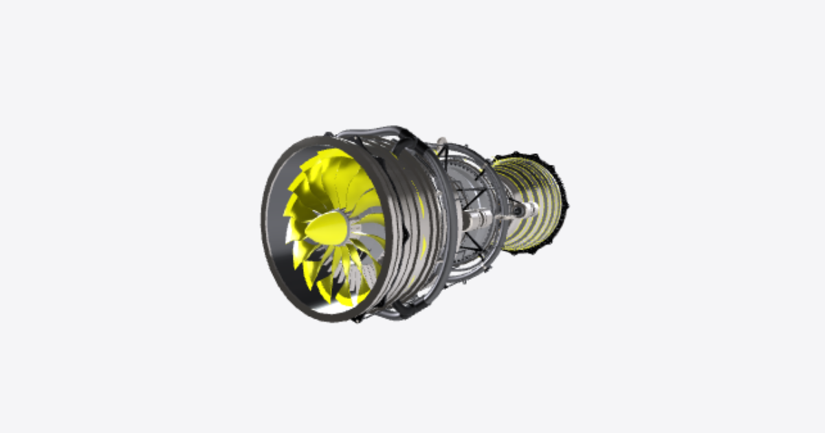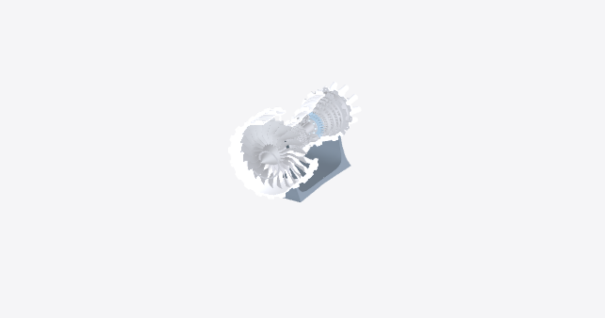
Step by step insturctions to assemble the engine
21 steps
Prepare the stand and assembly area
Place the stand on a clean, stable surface. Lay out the engine components in assembly order and inspect mating faces, bearing seats, blades and threads for dirt or damage. Keep all components supported and the assembly stationary. Do not connect power or fuel during assembly.
Position the high-pressure compressor
Support the high-pressure compressor on the engine centreline with its smaller compressor stages toward the turbine end. Keep the central bore clear and protect the blade edges. Maintain support until the bearing and casing supports are installed.
Mate the high-pressure turbine to the compressor
Bring the high-pressure turbine to the rear flange of the high-pressure compressor. Align the centre bore and the eight fastener positions. Bring the mating faces together evenly without using the fasteners to pull misaligned components into position.
Fit the eight screws and head-side washers
Place the eight head-side washers at the compressor-to-turbine joint, one under each screw head. Insert the eight screws through the aligned holes. Keep both rotor components supported and leave the screws loose until all positions are engaged.
Fit the remaining washers and nuts
Fit the eight nut-side washers and the eight nuts to the protruding screws. Start every nut by hand. Seat the joint progressively in an opposing pattern while restraining the screw heads. Keep the flange faces flush and check that no washer is trapped or omitted.
Position the two small bearing units
Keep the races and balls of the two small bearing units together. Position the forward small bearing at the compressor inlet and the aft small bearing at the high-pressure turbine bore, as highlighted. Keep each bearing square to its seat and apply fitting force only to the race being fitted, never through the balls.
Fit the front low-pressure shaft
Align the front low-pressure shaft with the central bore of the high-pressure spool. Guide it in from the fan end while supporting both ends. Keep the shaft concentric with the bearing bores and stop if it binds; do not force the shaft against a race or blade.
Fit the aft low-pressure spool
Bring the aft low-pressure spool in from the turbine end. Align its bore and forward mating features with the front shaft, then bring the components together without side loading the small bearings. Keep the shaft assembly supported.
Fit the low-pressure turbine
Align the low-pressure turbine with its seat on the aft spool. Guide it into position from the rear, keeping its stages concentric with the shaft. Seat the mating faces without pressing on the blade tips.
Position the front and rear large bearing units
Keep both large bearing units assembled. Fit the front unit at the fan-end shaft seat and the rear unit at the aft shaft seat. Keep the races square, support the shaft and avoid transmitting fitting force through the balls.
Fit the fan stator casing and support
Position the fan stator casing and support around the front bearing and shaft. Align the bearing seat, engine centreline and rear casing flange. Set the support onto the front stand location while maintaining support for the unfinished engine.
Fit the high-pressure compressor casing
Bring the high-pressure compressor casing around the compressor stages. Align its front flange with the fan stator support and its rear flange with the combustion section. Keep the casing clear of the blade edges and seat it without forcing.
Position the combustion lining
Position the combustion lining around the rear compressor section and ahead of the high-pressure turbine. Orient its injector openings to the outside of the engine and align its front and rear locating features. Keep the lining clear of the rotating components.
Fit the combustion and high-pressure turbine casing
Fit the combustion and high-pressure turbine casing around the lining. Align the front casing joint and the injector openings. Bring the mating faces together evenly, keeping the lining located and the injector openings unobstructed.
Fit the fuel injector assembly
Align the fuel injector assembly with the matching openings in the combustion casing and lining. Guide each injector tip into its opening without bending it. Seat the assembly evenly and keep all fuel passages clean and disconnected.
Fit the low-pressure turbine casing
Position the low-pressure turbine casing around the turbine stages. Align its front joint with the core casing and its rear bearing-support features with the aft shaft. Seat the casing at the rear stand location and keep it clear of the turbine blades.
Fit the fan
Support the fan at its hub and align the hub with the front low-pressure shaft. Guide it rearward onto its mating seat. Keep the blades clear of the stator support and do not use the blade tips as handles or levers.
Fit the fan casing
Bring the fan casing into position around the fan. Align its rear flange with the stator casing and support. Keep the casing clear of every blade tip and bring the joint faces together evenly.
Fit the exhaust nozzle
Align the exhaust nozzle with the rear turbine casing and the rear bearing seat. Guide the nozzle forward from the exhaust end and seat its front joint evenly. Keep the shaft and rear bearing supported while bringing the parts together.
Fit the exhaust mixer
Align the exhaust mixer with its matching nozzle features. Position the lobes evenly around the exhaust centreline and seat the mixer without distorting the thin edges. Check that adjacent lobes and the centrebody do not touch.
Inspect the completed assembly
- Check that the engine is seated stably on the stand and that all fitted joint faces are flush.
- Check the eight compressor-to-turbine screw positions for a screw, two washers and a nut at each position.
- Remove loose items from the inlet, core and exhaust.
- Gently turn the fan by hand at the hub. Check that the low-pressure turbine follows and stop immediately if there is rubbing, binding or unexpected movement.
- Leave fuel and power disconnected. This inspection does not authorize powered operation.