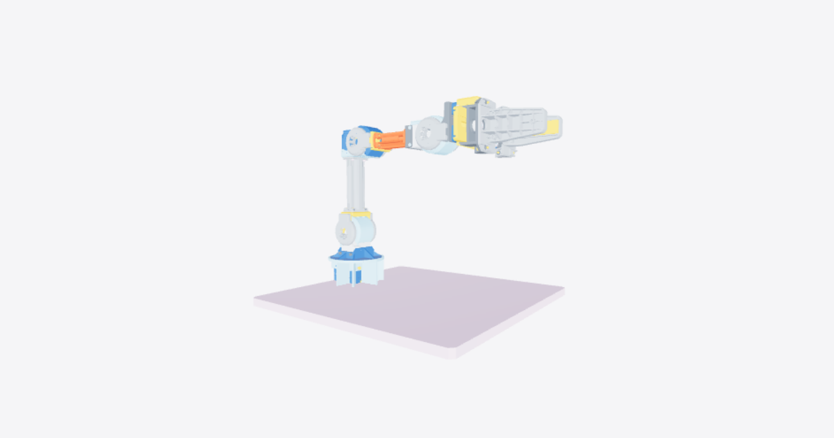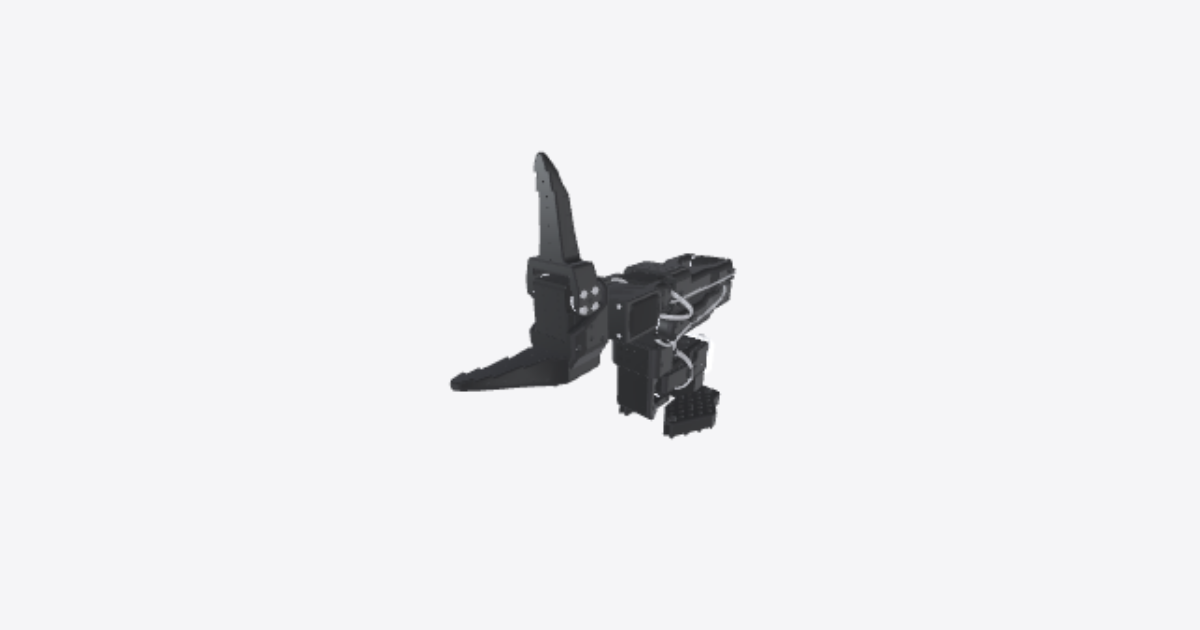
Full assembly
44 steps
Put the Base in place
Put the Base of the SO101 in place in order to assemble other parts on itPut in place the first servomotor
Put in place the first servomotor as shown. Tip: each servomotor needs its own ID (1 to 6, from the base up) before it goes into the arm, because all six share one cable bus. Set the IDs first, for example with LeRobot's motor setup command.Screw the servomotor in the Base
Screw the servomotor in the Base by screwing the 4 highlighted screws as shown.Put in the servomotor cover in place
Slide the highlighted cover onto servomotor 1 from the rear until it sits flush with the base and its two side screw holes line up.Screw the cover of the servomotor
Screw the cover of the servomotor in order not to movePut in place the rotation pitch part
Put in place the rotation pitch part on the servomotorScrew the Rotation Pitch
Screw the Rotation Pitch to the servomotor using the upper side screwsScrew the Rotation Pitch
Screw the Rotation Pitch to the servomotor using the lower side screwsAssemble the cover of the Rotation Pitch
Fit the highlighted cover onto the rotation pitch part so it sits flush and its edges line up with the part.Put in place the second servomotor
Insert servomotor 2 into the rotation pitch part in the orientation shown, with its output shaft on the side where the arm will attach. Route its cable so it will not be pinched by the arm.Screw the second servomotor
Screw the second servomotor in the Rotation PitchAssemble the arm
Assemble the arm on the second servomotorScrew the first set of screws
Fasten the first highlighted set of screws to fix the arm to servomotor 2. Tighten them evenly so the arm sits flat.Screw the second set of screws
Fasten the second highlighted set of screws on the other side of servomotor 2. The arm should now be held firmly on both sides with no play.Put in place the third servomotor
Insert servomotor 3 into the end of the arm in the orientation shown, with its output shaft on the side where the second arm will attach. Route its cable along the arm.Screw the third servomotor
Screw the third servomotor in the armAssemble the second arm
Place the second arm onto servomotor 3 in the orientation shown, so its screw holes line up with the servo on both sides.Screw the first set of screws
Screw the arm to the servomotor using the first set of screwsScrew the second set of screws
Fasten the second highlighted set of screws to finish fixing the second arm to servomotor 3.Assemble the part as shown
Assemble the part on the arm as shownPut in place the fourth servomotor
Insert servomotor 4 into the end of the second arm in the orientation shown. Route its cable along the arm so it will not be pinched.Screw the fourth servomotor
Screw the fourth servomotor to the armPut in place the part as shown
Put in place the part on the servomotor as shownScrew the part as shown
Screw the part using the screws as shownScrew the part as shown
Screw the part using the screws as shownPut in place the fifth servomotor
Slide servomotor 5 into the wrist bracket through its open side, in the orientation shown, with its output shaft facing the gripper end.Add the washer
Add the servomotor washerScrew the fifth servomotor
Fasten servomotor 5 to the wrist bracket with the highlighted screws. Tighten them evenly.Put in place the lower jaw
Place the lower (fixed) jaw onto the washer of servomotor 5 in the orientation shown, with its screw holes lined up.Screw the jaw to the washer and servomotor
Fasten the lower jaw to the washer of servomotor 5 with the first highlighted screws.Screw the jaw to the washer and servomotor
Fit the remaining highlighted screws to finish securing the lower jaw to the washer.Put in place the nuts
Press the two highlighted nuts into their recesses in the lower jaw so they sit flush. Do this now: they are hard to reach once servomotor 6 is in place.Put in place the sixth servomotor
Slide servomotor 6 (the gripper motor) into the lower jaw in the orientation shown, with its output shaft on the side where the moving jaw will attach.Screw the sixth servomotor
Fasten servomotor 6 to the lower jaw with the highlighted screws on both sides.Put in place the upper jaw
Place the moving (upper) jaw onto the output horn of servomotor 6 in the orientation shown.Screw the upper jaw
Fasten the moving jaw to the servo horn with the first highlighted set of screws.Screw the upper jaw
Fit the second set of screws to finish securing the moving jaw. Gently open and close the jaw by hand to check that it moves freely.Assemble the PCB
Fit the servo driver board (PCB) in its place at the base as shown, with its connectors accessible for the servo cable, power and USB.Plug the first servomotor to the PCB
Connect a 3-pin servo cable from the driver board to servomotor 1.Plug the first servomotor to the second servomotor
Connect servomotor 1 to servomotor 2 with a 3-pin cable. The servos are daisy-chained: each has two identical ports, so either port can be used.Plug the second servomotor to the third servomotor
Connect servomotor 2 to servomotor 3. Route the cable along the arm, leaving enough slack for the shoulder and elbow to move through their full range.Plug the third servomotor to the fourth servomotor
Connect servomotor 3 to servomotor 4. Leave enough slack at the elbow and wrist for full movement.Plug the fourth servomotor to the fifth servomotor
Connect servomotor 4 to servomotor 5. Leave enough slack at the wrist for full movement.Plug the fifth servomotor to the sixth servomotor
Connect servomotor 5 to servomotor 6. Gently move each joint by hand through its full range to check that no cable is pulled or pinched. Before first use, power the board and calibrate the arm (for example with LeRobot's calibration command).