TwinWorks
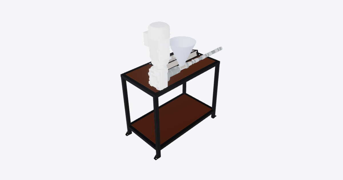
Precious Plastic extrusion machine – 3D model preview

Precious Plastic extrusion machine

Téa · Industrial · 3D model · Updated 6 Nov 2026

Open in 3D

  • Procedures4shared publicly
  • Views0all time
  • Rating–No ratings yet
  • Likes0from the Community

0 comments

Procedures

1. Bearing body and drive shaft

Assembly · 12 steps · No ratings yet

12 steps
  1. Prepare the bearing body

    Begin the bearing body and drive shaft assembly, the first stage of the Precious Plastic Extruder Pro V1 build.

    Clean the bearing body, its bearing seats and seal recesses. Remove loose debris and inspect the seating surfaces for burrs or damage. Support the body securely with both ends accessible and the grease port oriented as shown.

    Credit: based on the Precious Plastic Extruder Pro V1 by Precious Plastic / One Army (preciousplastic.com), licensed CC BY-SA 4.0 (creativecommons.org/licenses/by-sa/4.0). Adapted by TwinWorks; this guide is shared under the same licence.

  2. Fit the inlet-side bearing and coupling shaft

    Fit the inlet-side 32006X taper roller bearing onto the coupling shaft in the orientation shown. Introduce the shaft and bearing into the bearing body from the transition-piece side, keeping them coaxial. Seat the bearing against its housing shoulder and the shaft against its bearing seat.

    Apply fitting force only to the ring being fitted. Do not transmit fitting force through the rollers or strike the shaft.

  3. Fit the coupling-side taper roller bearing

    Fit the coupling-side 32006X taper roller bearing over the free end of the coupling shaft and into the bearing body. Keep its taper opposed to the inlet-side bearing, matching the model's orientation. Seat the bearing squarely without transmitting fitting force through the rollers.

  4. Fit the inlet-side radial shaft seal

    Guide the inlet-side radial shaft seal over the shaft and into the inlet-side recess of the bearing body. Preserve the lip orientation shown in the model. Protect the sealing lip from edges and seat the seal squarely by its outer rim, without folding or cutting the lip.

  5. Fit the seal bearing spacer

    Slide the seal bearing spacer over the coupling end of the shaft. Seat it against the coupling-side bearing in the position shown, with its seal-running surface aligned with the coupling-side seal recess. Keep the spacer square and its running surface clean and undamaged.

  6. Fit the coupling-side radial shaft seal

    Fit the coupling-side radial shaft seal into the remaining bearing-body recess, guiding its lip onto the spacer's running surface. Match the orientation shown in the model. Seat the outer rim evenly and check that the sealing lip is not folded or trapped.

  7. Fit the shaft clamp

    Slide the shaft clamp onto the coupling shaft and position it immediately outside the seal bearing spacer, as shown. Keep the clamp square and its clamping feature accessible. Secure the clamp using its own clamping feature without driving it against the seal.

  8. Fit the transition piece to the bearing body

    Bring the transition piece onto the inlet end of the bearing body. Align the mating register and keep the central passage coaxial with the shaft. Seat the mating faces in the positions shown without disturbing the inlet-side seal.

  9. Install the grease nipple

    Install the grease nipple in the radial grease port of the bearing body, in the orientation shown. Start it by hand to avoid cross-threading, then secure it at its hexagonal base. Leave the nipple accessible and keep dirt out of the grease passage.

  10. Assemble and fit the barrel inlet

    Position barrel flange 1 at the bearing-body end of the barrel inlet and barrel flange 2 at its opposite end, following the barrel-inlet sub-assembly order and the seating positions shown. Keep the inlet opening oriented as in the model.

    Bring the barrel-inlet assembly to the transition piece. Engage the flange 1 register, align the screw holes and seat the mating faces squarely. Support the inlet while the screws are fitted. Leave flange 2's downstream connection free for the later barrel assembly.

  11. Fasten the barrel inlet to the transition piece

    Fit the 12 M6 × 20 DIN 912 socket head screws shown around barrel flange 1. Start every screw by hand into the transition piece before tightening any one screw fully.

    Draw the joint together progressively, alternating around the flange so that the faces remain square and fully seated. Do not use the screws to force a misaligned register into place.

  12. Inspect the completed bearing and inlet assembly

    Check that the bearing body and transition piece are seated together, both bearings and seals are square, and the seal bearing spacer and shaft clamp match the positions shown. Check that the grease nipple is secure and accessible.

    Support the assembly and turn the coupling shaft slowly by hand. Check for smooth movement without binding or scraping. Inspect the barrel inlet, both flanges and the twelve inlet-joint screws for alignment and complete seating. Keep the assembly supported for the next build stage.
2. Barrel, screw and nozzle

Assembly · 8 steps · No ratings yet

8 steps
  1. Prepare the barrel, screw and nozzle components

    Begin after the bearing body and barrel inlet have been assembled. Keep the machine unpowered and the components cold.

    Lay out the barrel, barrel flange and barrel tip for assembly 1140.00, the extrusion screw, screw tip, clip bushing, intermediate nozzle and twelve M6 × 16 DIN 912 socket head screws. Clean the bores and mating faces and remove loose debris. Support the long components throughout assembly.

  2. Fit the barrel and barrel flange

    Position the barrel flange 1140.02 at the inlet end of the barrel 1140.01, forming the inlet end of barrel group 1140.00. Keep the bores concentric and orient the flange holes as shown.

    Support the barrel in line with the previously assembled barrel inlet, with the flange faces together. Leave the barrel tip and nozzle off to provide access for screw insertion. Keep the barrel supported until the flange screws are fitted.

  3. Position the clip bushing at the drive end

    Fit the clip bushing at the drive-shaft end, in the position shown around the coupling shaft. Align its bore with the screw axis before inserting the extrusion screw. Keep the bushing accessible until the screw is seated.

  4. Fit the screw tip and insert the extrusion screw

    Fit the screw tip to the discharge end of the extrusion screw in the orientation shown. Use the specified 30 mm diameter, 600 mm long extrusion screw.

    Support the screw and tip together and slide them axially into the barrel from the open discharge end, with the drive end entering first. Guide the drive end into the existing coupling shaft and clip bushing. Do not hammer the screw or force it through a tight spot. Seat the screw and tip in the positions shown, then secure the clip bushing on the drive end.

  5. Bolt the barrel flange to the barrel inlet

    Keep the barrel group supported and align the barrel flange with the mating flange on the existing barrel inlet. Ensure the mating faces sit together without trapping debris.

    Install all twelve M6 × 16 DIN 912 socket head screws in the positions shown, with their heads on the barrel side. Start every screw by hand. Tighten progressively in an opposing pattern so the flange seats evenly. Do not use the screws to pull a misaligned barrel into place.

  6. Fit the barrel tip

    Fit the barrel tip 1140.03 over the screw tip at the discharge end of the barrel. Keep its bore concentric with the screw and seat it in the orientation shown, completing barrel group 1140.00. Leave the internal flow passage clear of debris.

  7. Fit the intermediate nozzle

    Fit the intermediate nozzle 1100.01 to the barrel tip at the discharge end. Keep the nozzle concentric with the barrel and seat it in the orientation shown. Keep the outlet and internal flow passage clear of debris.

  8. Check the completed barrel assembly

    Check that the barrel group is aligned with the inlet, the flange faces are seated evenly and all twelve flange screws are installed. Check that the screw tip, clip bushing and intermediate nozzle are seated in their shown positions.

    With power isolated, check that the extrusion screw can be turned manually without binding. Stop if it rubs or jams. Keep the machine unpowered at the end of this procedure.

3. Drive, hopper and heaters

Assembly · 8 steps · No ratings yet

8 steps
  1. Prepare the drive, hopper and heating components

    Begin this third assembly stage after completing the barrel. Keep the machine disconnected from electrical power and the barrel cold throughout assembly.

    Stage the gearbox flange group, BAZ39 geared motor, cone clamp rated for at least 250 Nm, cone hopper with cork insulation and two 50 mm hose clamps, five 40 mm diameter × 50 mm wide band heaters, one 40 mm diameter × 20 mm wide band heater, and three J-type thermocouples.

    Keep the completed bearing body, coupling shaft and barrel assembly in place. This stage covers mechanical fitting only, not electrical connection or commissioning.

  2. Fit the gearbox flange group, drawing 1110.00

    Fit the gearbox flange group between the completed bearing body and the geared motor position.

    1. Place the screw-side flange (Flange 1) against the bearing body, with its central opening concentric with the coupling shaft.
    2. Fit the flange spacer between the two flange plates.
    3. Place the motor-side flange (Flange 2) toward the gearbox, matching the orientation and hole pattern shown.

    Keep the faces seated squarely and the central passage clear. The motor is fitted in the next step.

  3. Mount the BAZ39 geared motor

    Support the BAZ39 geared motor throughout positioning. Bring its hollow 30 mm output shaft into line with the installed coupling shaft and the gearbox flange group.

    Move the gearbox onto the coupling shaft without hammering or using the joint to pull misaligned parts together. Seat the gearbox squarely against the motor-side flange in the orientation shown. Secure the flange group and the motor in their mounted positions before releasing the motor support.

    Leave the shaft-locking connection loose until the motor and flange faces are aligned.

  4. Fit and lock the cone clamp

    Use a cone clamp with a transmitted-torque rating of at least 250 Nm. This rating is not a clamp-screw tightening torque.

    Position the clamp at the coupling-shaft connection shown. With the motor and flange group aligned, tighten the clamp evenly in stages to lock the coupling shaft to the gearbox output. Keep the mating faces seated and do not disturb the shaft alignment.

    Check that the connection is secure before proceeding.

  5. Fit the insulated cone hopper, drawing 1200.00

    Fit the cone hopper at the barrel inlet in the orientation shown.

    1. Place the cork insulation between the barrel inlet and the hopper mounting pieces, leaving the feed opening unobstructed.
    2. Seat the hopper mounting pieces around the inlet and align the cone outlet with the feed opening.
    3. Position both 50 mm hose clamps around the mounting assembly, one on each side of the feed opening as shown.
    4. Tighten the clamps progressively so the hopper is stable without crushing or displacing the cork insulation.

    Check that the hopper stands upright and the feed passage remains clear.

  6. Fit the five full-width band heaters

    Fit the five 40 mm diameter × 50 mm wide band heaters along the barrel at the five positions shown, working from the hopper end toward the outlet.

    Loosen each heater band enough to fit it without forcing it. Seat each band evenly against the barrel and tighten its integral closure so it is secure. Leave the thermocouple positions accessible and keep the heater connections clear of the hopper and moving drive parts.

    Keep all heaters electrically disconnected.

  7. Fit the short outlet band heater

    Fit the short 40 mm diameter × 20 mm wide band heater around the nozzle at the barrel outlet, at the position shown.

    Seat the band evenly, secure its integral closure and keep the outlet opening clear. Leave its electrical connection accessible and disconnected.

  8. Fit the three J-type thermocouples

    Fit the three J-type thermocouples at the positions shown: the inlet-side barrel position, the intermediate barrel position and the outlet-tip position.

    Seat each sensing end at its mounting location and secure its integral mounting band without bending or damaging the probe. Keep the sensor leads clear of heater closures and the drive, and leave them electrically disconnected.

    Check that all six heater bands and all three thermocouples are secure, the hopper feed path is clear and the drive connection remains aligned. Do not energize the assembly at this stage.

4. Frame, electronics and first heat-up

Assembly · 9 steps · No ratings yet

Tools

  • fire extinguisher

Protective equipment

  • heat-proof gloves
  • coverall
  • sealed glasses or a face shield
  • respirator with ABEK1 filters
  • closed shoes

Warning: Only a licensed electrician may wire or open the electronics box.

Notice: Incorrect star or delta motor wiring can burn out the motor; the thermocouple type must match the controllers.

Warning: Parts reach up to 350 °C. Wear the specified protective equipment.

Warning: Run fume extraction at all times; never process PET or PVC.

Warning: Never stand in front of the nozzle.

Warning: Keep a fire extinguisher nearby.

9 steps
  1. Fabricate and inspect the steel frame

    Build the main frame for drawing 3000.00 from 40 × 40 mm steel tube, matching the arrangement shown. Cut and deburr the members, clamp the structure square and tack-weld the joints. Recheck squareness and the shelf support positions before completing the welds. Allow the frame to cool, remove sharp edges and check that it stands firmly without rocking.

    Keep the plywood shelves and electrical equipment away from cutting and welding work. Use appropriate welding protection and local exhaust ventilation.

  2. Fit the bottom plywood shelf

    Place the bottom plywood shelf onto the lower supports of the main frame. Seat it flat within the frame without forcing it, and check that it is fully supported and does not rock.

  3. Fit and align the top plywood shelf

    Lower the top plywood shelf onto the upper supports of the main frame. Align its mounting holes with the frame holes. Check that it lies flat and that the extruder mounting positions remain unobstructed.

  4. Mount the extruder on the frame

    Keep the machine disconnected from electrical power. Support the assembled extruder with suitable lifting equipment and position it on the top plywood shelf, aligning its mounting holes with the main frame. Keep hands clear beneath the load.

    Install four M8x45 screws, eight M8 washers and four M8 nuts. Use one washer beneath each screw head and one beneath each nut, following the arrangement shown. Keep the load supported until all four fasteners are engaged. Tighten evenly and check that the extruder is secure and the frame remains stable.

  5. Mount the electronics box and support

    Keep electrical power disconnected. Support the electronics box and its support as one unit and align the support with the mounting positions on the main frame.

    Secure the support using four M6x35 screws, eight M6 washers and four M6 nuts. Use one washer beneath each screw head and one beneath each nut, following the arrangement shown. Position the box before inserting the fasteners, then tighten evenly. Check that the box is secure and its controls remain accessible.

  6. Have a licensed electrician complete the electrical installation

    Only a licensed electrician may open or wire the electronics box. Isolate the electrical supply and verify that the equipment is de-energized before opening it.

    The electronics box must house three REX-C100 temperature controllers, three 40 A solid-state relays, the motor speed drive, emergency stop and contactor. Have the electrician complete and test the installation, including protective earthing and emergency-stop operation, before heat-up.

    The electrician must select the motor's star or delta connection to suit its nameplate and the drive output. Incorrect wiring can burn out the motor. Match the thermocouple type to the controller input configuration. Close and secure the box before energizing it.

  7. Prepare the first heat-up safely

    Check that the frame is stable, the extruder and electronics box are secure, and electrical commissioning is complete. Keep the motor stopped.

    • Wear heat-proof gloves, a coverall, sealed glasses or a face shield, a respirator with ABEK1 filters and closed shoes.
    • Start fume extraction before heating and keep it running throughout heat-up and operation.
    • Keep a fire extinguisher nearby and keep combustible materials away from hot parts.
    • Keep everyone out of the area directly in front of the nozzle.
    • Never process PET or PVC.

    Parts can reach up to 350 °C. This is a burn-hazard temperature, not a heat-up setpoint.

  8. Heat the barrel and allow five minutes to soak

    With the motor stopped and fume extraction running, use the electronics box controls to set each heating zone to the operating temperature for the intended permitted plastic. Switch on the heaters and monitor all three temperature controllers.

    Bring the barrel up to temperature before starting the motor. Once all zones have reached their operating temperatures, wait five more minutes to allow the barrel to heat through. Keep the motor stopped for the entire waiting period.

    Keep wearing the specified protective equipment and stay out of the area in front of the nozzle. If temperatures behave abnormally or extraction fails, stop heating and keep the motor stopped. Only a licensed electrician may open the box to investigate electrical faults.

  9. Start the motor only after the heat soak

    Check that all heating zones remain at their operating temperatures and that the additional five-minute waiting period is complete. Keep the electronics box closed.

    With fume extraction running, the specified protective equipment worn and everyone clear of the nozzle front, start the motor using the speed drive controls. Monitor the machine from a safe position. Stop immediately if operation is abnormal, and isolate the supply before any intervention. Never feed PET or PVC.

Related products

  • Precious Plastic shredder

    Téa

    Industrial · 3D model · 4 procedures

    No ratings yet

    0 likes · 0 comments · 0 views

  • Helicopter Rotor

    Mina

    Industrial · 3D model · 1 procedure

    No ratings yet

    0 likes · 0 comments · 1 view

  • V8 Engine

    Mina

    Industrial · 3D model · 1 procedure

    No ratings yet

    0 likes · 0 comments · 0 views

  • Boxer Engine

    Téa

    Industrial · 3D model · 1 procedure

    No ratings yet

    0 likes · 0 comments · 2 views