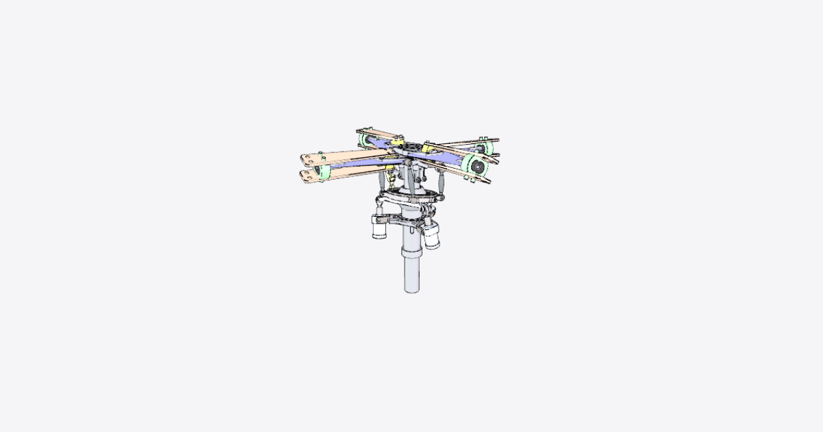
Assembly
Warning: Keep the rotor drive and actuators isolated from power during assembly.
Warning: The 3D arrangement does not establish fastening, locking, preload or airworthiness requirements. Do not power or operate the rotor on the basis of this assembly sequence alone.
Caution: Keep hands clear of closing gaps between the grip, linkage and swashplate components.
42 steps
Prepare and inspect the rotor components
Keep the rotor drive and actuators isolated from power throughout assembly. Support the rotor shaft securely and inspect its bearing seats and mating surfaces for damage, burrs and contamination.
Lay out the components by subassembly and keep paired components together. Keep bearing, spherical and pivot surfaces clean. Do not assemble damaged components.
Fit the rotating swashplate ring
Position the rotating ring around the bare shaft in the orientation shown. Keep the spherical support, stationary body and upper plate off while bringing the ring into position. Support the ring until the surrounding swashplate components are fitted.
Fit the spherical swashplate support
Bring the spherical support into position from below with its bore aligned to the shaft. Keep the stationary body, actuator support plate and guide sleeve off during this movement. Support the spherical component and protect its mating surface from impact and contamination.
Fit the stationary swashplate body
Bring the stationary swashplate body upward from immediately below the spherical support, keeping its bore aligned with the spherical interface. Orient the three actuator attachment stations as shown. Leave the actuators and their support members off until the body is seated.
Seat the interface evenly without forcing it or scraping the spherical surface.
Fit the actuator support plate
Bring the actuator support plate into position from below, around the bare shaft. Keep the guide sleeve and actuator components off during this movement. Orient the three mounting stations as shown and support the plate until the central sleeve is fitted.
Fit the guide sleeve to the shaft
Insert the guide sleeve from below along the rotor shaft and through the aligned central interfaces of the support plate and spherical support. Preserve the orientation of its longitudinal slot. Seat the sleeve without scoring the mating surfaces, then check that the supported components remain correctly seated.
Assemble stationary pivot station 1
- Position the first pivot lever at its stationary swashplate station.
- Align the crosspiece with the lever and housing interfaces.
- Fit both side pieces in their shown positions without trapping or cocking the pivot.
- Check that the joint articulates freely.
Assemble stationary pivot station 2
- Position the second pivot lever at the next stationary swashplate station.
- Align the crosspiece and fit both side pieces in the orientation shown.
- Seat the interfaces evenly and check free articulation without contact with the adjacent station.
Assemble stationary pivot station 3
- Position the third pivot lever at the remaining stationary swashplate station.
- Align the crosspiece and fit both side pieces in the orientation shown.
- Check that all three stationary pivot stations are seated and articulate without binding.
Fit the upper swashplate plate
Position the upper swashplate plate concentrically over the ring assembly. Match its attachment features to the orientation shown and seat the mating face evenly. Leave access to the peripheral pivot stations.
Assemble upper pivot station 1
Position the first upper pivot lever at its plate attachment. Fit its mating pivot piece in the orientation shown. Seat the joint without forcing the alignment and check free articulation.
Assemble upper pivot station 2
Position the second upper pivot lever at its plate attachment. Fit its mating pivot piece in the orientation shown. Check that the two upper pivot stations articulate independently without contacting the ring.
Fit the remaining upper pivot pieces
Fit the two remaining upper pivot pieces at their respective plate stations. Preserve the handed orientation shown, align the pivot interfaces and check that the pieces clear the neighboring attachments.
Fit the upper annular ring
Bring the upper annular ring down along the swashplate's own axis from immediately above its mating face, rather than sliding it sideways across the central support. Align its peripheral features and seat the ring evenly. Keep the central connecting linkage and hubs off during fitting.
Assemble actuator station 1
- Position the first actuator support member at its mounting station.
- Align the actuator moving member with its guide and plate attachment.
- Fit the actuator body around its mating member in the orientation shown.
- Seat the mounting interfaces without side-loading the moving member. Check that its path is unobstructed.
Assemble actuator station 2
- Position the second actuator support member at its mounting station.
- Align the actuator moving member with its guide and plate attachment.
- Fit the actuator body in the orientation shown.
- Seat the interfaces without side-loading the moving member and check clearance from the first station.
Assemble actuator station 3
- Position the third actuator support member at the remaining mounting station.
- Align the actuator moving member with its guide and plate attachment.
- Fit the actuator body in the orientation shown.
- Check all three actuator stations for seated interfaces, clear moving members and correct attachment orientation. Keep the actuators unpowered.
Fit the lower drive lever
Position the lower drive lever at its shaft-side interface in the orientation shown. Align the mating features without using the lever to pull the assembly into place. Keep the free end accessible for the connecting linkage.
Fit the paired drive-link levers
Position the two drive-link levers on their respective sides of the central linkage. Preserve their opposed orientations and align the pivot interfaces shown. Check that neither lever is trapped against the shaft.
Complete the central connecting lever
Position the inner connecting-lever component between its mating linkage interfaces, then fit the outer connecting-lever component. Align the joint axes without forcing the levers sideways. Check that the completed linkage articulates and clears the shaft and swashplate.
Fit the first rotor hub member
Support the first hub member and align its central bore with the rotor shaft. Bring it into the installed position with its two radial attachment arms oriented as shown. Seat the central interface evenly without loading the swashplate below.
Fit the second rotor hub member
Align the second hub member with the shaft and the first hub member. Match the crossed arrangement shown, keeping the four radial attachment stations distinct. Seat the mating interfaces without forcing or distorting either hub member.
Fit the first pair of spherical hub components
Fit the first pair of spherical hub components to the two corresponding radial interfaces of the first hub member. Preserve their opposed orientations and seat each spherical interface evenly. Protect the spherical surfaces from impact.
Fit the second pair of spherical hub components
Fit the second pair of spherical hub components to the two radial interfaces of the second hub member. Match the shown orientation and seat the interfaces evenly. Check that all four radial stations remain clear for the grip components.
Fit rotor arm components at station 1
Position the first radial arm component at its first-hub attachment. Fit the mating arm component in the orientation shown. Align the inboard and outboard interfaces without bending the arm to make the holes line up.
Fit rotor arm components at station 2
Position the second radial arm component at the opposite first-hub attachment. Fit the mating arm component as shown. Keep the opposed arm arrangement symmetrical and avoid twisting the components during seating.
Fit rotor arm components at station 3
Position the third radial arm component at its second-hub attachment. Fit the mating arm component as shown. Align both attachment interfaces without bending or twisting the arm.
Fit rotor arm components at station 4
Position the fourth radial arm component at the remaining second-hub attachment. Fit the mating arm component as shown. Check the complete four-arm arrangement for correct orientation, seated interfaces and clearance from the central linkage.
Fit grip 1 inboard components
- Position the first grip pitch lever at its inboard interface.
- Seat the inboard bearing component in the shown orientation.
- Fit both grip side members around the mating radial arm.
- Keep the pitch lever oriented toward its pitch-link connection and align the two side members without pinching the bearing interface.
Complete grip 1 outboard bearing assembly
Fit the outboard housing component between the first grip side members. Seat the mating bearing component and fit the inner sleeve concentrically as shown. Check that the outboard assembly is seated without distorting the side members and that the grip can articulate without binding.
Fit grip 2 inboard components
Position the second grip pitch lever, seat the inboard bearing component, and fit both grip side members around their mating radial arm. Match the shown orientation rather than copying the first grip's handedness. Align the bearing interfaces and keep the pitch-link attachment accessible.
Complete grip 2 outboard bearing assembly
Fit the outboard housing component, seat the mating bearing component and fit the inner sleeve concentrically between the second grip side members. Match the shown stack orientation and check that the grip articulates without binding.
Fit grip 3 inboard components
Position the third grip pitch lever, seat the inboard bearing component and fit both grip side members around their mating radial arm. Preserve the shown handedness and align the interfaces without forcing the side members apart.
Complete grip 3 outboard bearing assembly
Fit the outboard housing component, seat the mating bearing component and fit the inner sleeve concentrically between the third grip side members. Check seating around each interface and verify free articulation without loading the neighboring arm.
Fit grip 4 inboard components
Position the fourth grip pitch lever, seat the inboard bearing component and fit both grip side members at the remaining radial station. Match the orientation shown. Check that all four pitch levers face their intended link connections and that no grip is reversed.
Complete grip 4 outboard bearing assembly
Fit the outboard housing component, seat the mating bearing component and fit the inner sleeve concentrically between the fourth grip side members. Check that each of the four grip bearing assemblies is seated and that no side member is bowed or trapped.
Assemble and connect type-1 pitch link 1
Position the first type-1 link body along the connection path shown. Fit both spherical end components to their respective link interfaces and connect the ends at the indicated swashplate and pitch-lever stations.
Keep the spherical joints aligned without twisting the link or using it to pull the grip into position. Check that both joints articulate freely.
Assemble and connect type-1 pitch link 2
Position the second type-1 link body along its shown connection path. Fit both spherical end components and connect them to the corresponding swashplate and pitch-lever stations. Keep this link separate from the neighboring link path.
Check free spherical-joint articulation and clearance from the hub, arm and grip.
Assemble and connect pitch link 3
Position the third link body along its shown connection path. Fit both spherical end components to the corresponding interfaces and connect the swashplate and pitch-lever ends without forcing either joint.
Check that the link is not crossed with an adjacent link and that both ends retain free articulation.
Assemble and connect pitch link 4
Position the fourth link body at the remaining connection path. Fit both spherical end components and connect them to their respective swashplate and pitch-lever interfaces.
Check the complete set of four links for correct routing, seated joint interfaces and clearance from the central drive linkage.
Inspect the completed assembly and retention
Inspect the rotor assembly from the shaft support upward.
- Check the support plate, spherical support and swashplate interfaces for full seating.
- Inspect the three actuator stations and central drive linkage for aligned connections.
- Check both hub members, all four arm stations, grip bearing stacks and pitch links for correct orientation.
- Inspect each connection for its required fasteners and locking features. Do not regard a seated component as secured solely because it matches the 3D position.
- Remove loose items and keep the drive and actuators isolated.
Check unpowered articulation and clearance
With the rotor drive and actuators isolated, gently check accessible joints for free articulation within the movement permitted by their restraints. Do not force a powered actuator or drive train by hand.
- Check the swashplate interfaces and central linkage for rubbing or binding.
- Check each grip and pitch-link joint for smooth articulation without side-loading.
- Check clearance between neighboring arms, grip components, links and the shaft.
- Stop if a connection binds, separates or contacts an adjacent component. Keep the assembly unpowered.
This check is not a powered test or a release for operation.