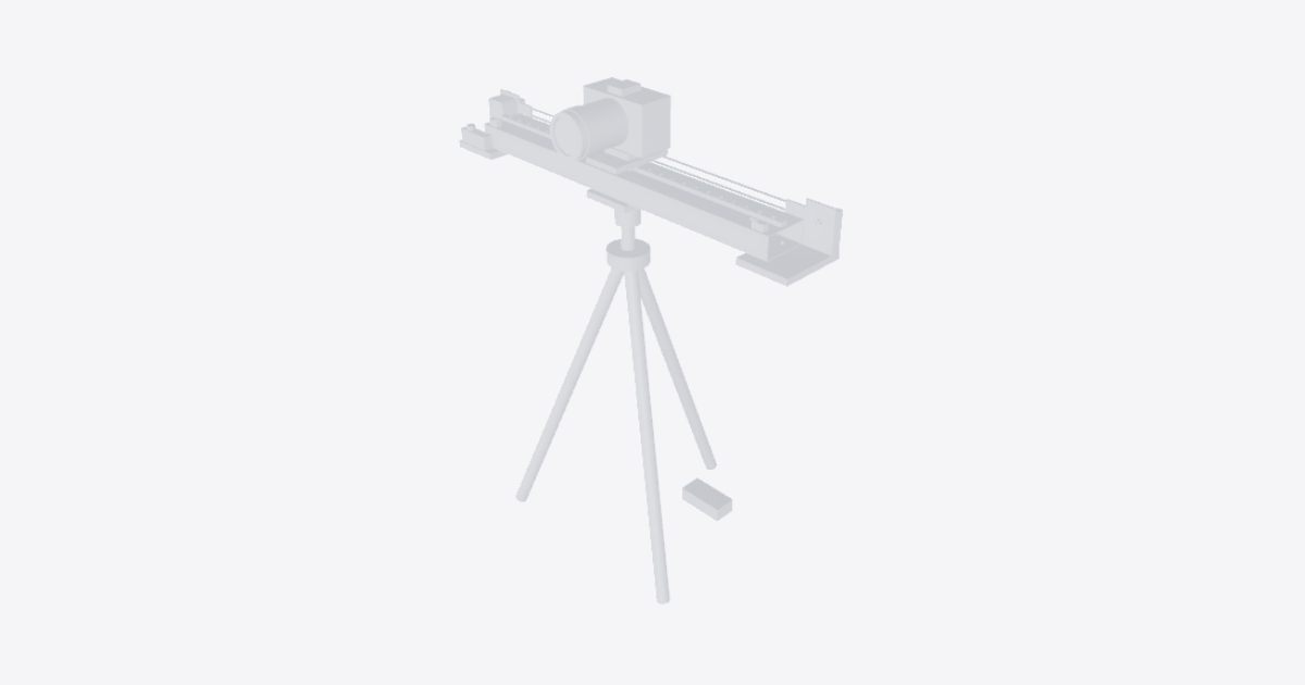
Create an assembly procedure for the Motorized Camera Slider
Tools
- Straightedge
- Driver matched to the rail fasteners
- Driver matched to carriage and clamp hardware
- Hex key matched to the M5×12 screws
- Hex key matched to the M3×8 screws
- Driver matched to the idler axle screw and keeper hardware
- Driver matched to guard, switch and controller mounting hardware
- Level
- Tape measure
- Driver matched to the camera plate fastener
Caution: Keep fingers clear of belt and pulley pinch points
Caution: Support the slider until the tripod attachment is locked
Caution: Keep hands clear during powered travel
Caution: Support the camera until the clamp is locked
10 steps
Prepare the extrusion and isolate power
Support the 4080 aluminum extrusion horizontally on a flat, stable bench, with room to reach its underside without letting it roll or tip. Keep the 12 V adapter disconnected and keep the camera off the slider until the unloaded test passes.
Lay out the parts and fasteners by assembly. Inspect the extrusion and guide surfaces for burrs, dirt or damage; clean the mating faces and do not assemble damaged parts. Keep any bearing transfer rail with the guide block until installation.
Seat and align the MGN12 guide rail
Seat the MGN12 guide rail flat along the center of the 4080 aluminum extrusion. Leave both ends open. Start the rail fasteners without tightening them fully. Use a straightedge along the extrusion to check that the rail is straight and parallel to it. Tighten the fasteners gradually from the center outward with the matching driver; recheck alignment and make sure no screw head protrudes into the guide block’s path.
Load the guide block and fit the carriage
With the rail end still open, transfer the MGN12H guide block onto the rail from its bearing transfer rail, keeping both rails aligned and in contact. If the block is already on the rail, leave it there. Do not force the block or let it run off either end.
Fasten the PETG camera carriage to the block using the matching driver. Fit the clamp from the Arca quick-release clamp and plate assembly to the carriage and leave the plate empty. Before attaching the belt, move the unloaded carriage slowly by hand through the intended travel, staying clear of the open rail ends. It must move smoothly without binding, scraping or unexpected play. If it binds, recheck rail seating and alignment before continuing.
Fit and square the end supports
Fit the PETG motor mount and left end support at the drive end and the PETG tensioner and right end support at the idler end. Start the four M5×12 socket-head screws from below, two per support, with a matching hex key. Seat the supports square to the extrusion, then tighten evenly without distorting the PETG. Fit the four rubber foot pads to the underside of the supports. Set the slider on a flat bench: all pads must sit firmly without rocking, and the carriage must still move freely within its intended range.
Mount the NEMA 17 motor and GT2 drive pulley
Keep power disconnected. Seat the NEMA 17 stepper on the left support with its shaft facing the belt path. Start the four M3×8 socket-head screws by hand, then tighten them evenly with a matching hex key. Verify that the motor seats flush and that the screws clamp the mount without bottoming.
Slide the GT2 motor pulley onto the shaft with the belt path unobstructed. Set its axial position to line up with the idler and secure it using the pulley’s fitted retaining feature. Check that it turns without rubbing; recheck alignment after fitting the idler.
Install the idler, route the belt and set tension
- Fit the GT2 bearing idler at the right support with the idler axle screw and a matching driver. Make sure the bearing spins freely. Keep the tension adjustment slack for fitting the belt.
- Loop the GT2 closed-loop timing belt around the motor pulley and idler without twisting or prying it into place. Engage the teeth with the drive pulley. Seat the upper run at the carriage with the PETG belt keeper; the return run must stay free.
- Align the pulley and idler so both belt runs are straight. Take up slack with the right-end tensioner, then secure the adjustment without overtensioning. With power still disconnected, move the carriage slowly by hand through the intended range. The belt must track without climbing, rubbing, skipping or shifting in the keeper. Stop if it binds; recheck alignment and tension.
Fit pulley guards and check both limit switches
With power disconnected, secure the motor pulley guard and idler pulley guard. Check that neither fouls the belt. Install the motor-end roller limit switch and idler-end roller limit switch. Slowly bring the unloaded carriage toward each end by hand and check that it actuates the roller before any hard contact or risk of running off the rail. Do not use a collision with an end support as a stop.
Secure the stepper speed controller at the motor end. Use only the verified matching motor and switch connections; keep leads out of the carriage, belt and pulley paths. If the connections or switch action cannot be verified, leave the power disconnected.
Secure the center saddle and check tripod stability
Support the unloaded slider while fitting the aluminum center tripod saddle beneath the extrusion. Start all four M5×12 socket-head screws and tighten evenly with a matching hex key. Check that the saddle seats flat and cannot shift.
Set the video tripod and head on firm, level ground. Spread and lock the legs and lock the head. Use a compatible tripod attachment that clamps the saddle without bottoming. Verify that the tripod and head are rated for the complete setup, not just the camera. Support the slider until the head attachment is locked. Use a level to check that the guide rail is horizontal. With the camera still off, check stability at the center and near both ends of intended carriage travel. Stop if any foot lifts or slips, the head creeps, or the saddle rocks or rotates.
Test approximately 500 mm of horizontal travel unloaded
- With the slider horizontal and the camera off, park the carriage near mid-travel. Mark the intended endpoints with a tape measure, approximately 500 mm apart and clear of hard contact at both ends. Do not extend travel to reach the target if safe clearance is insufficient.
- Keep hands clear and the stop control within reach. Connect the external 12 V power adapter only after verifying compatibility. Set the stepper speed controller to its lowest controllable speed. Jog a short distance in each direction, then verify that both limit switches stop motion toward their respective ends before hard contact. Stop immediately if either switch fails or the carriage approaches an obstruction.
- Run the intended stroke in both directions at low speed. Observe belt tracking, carriage motion, and tripod feet and head. Stop for binding, rubbing, belt drift or skipping, cable interference, or any movement at the tripod interface. Stop at the end of the test and record the safe travel between endpoint positions using the same reference on the carriage. Proceed only if the checks pass. Return the carriage to mid-travel and disconnect power.
Mount the 1.2 kg camera after the unloaded test passes
With power disconnected and the carriage centered, fasten the plate from the Arca quick-release clamp and plate assembly to the 1.2 kg camera and lens using the compatible camera attachment and matching driver. Support the camera while fully engaging the plate and locking the clamp. Check that the camera cannot lift, slide or twist in the clamp before letting go.
Recheck that the head and saddle stay locked and that the tripod does not rock or tip as the loaded carriage moves slowly by hand within the verified travel. Keep a hand ready to support the camera, and stop if a foot unloads, the head creeps, or the mount shifts. Do not power the loaded slider until the stability check passes.