Step-by-step assembly of the 2020 frame
10 steps
Build the 2020 base
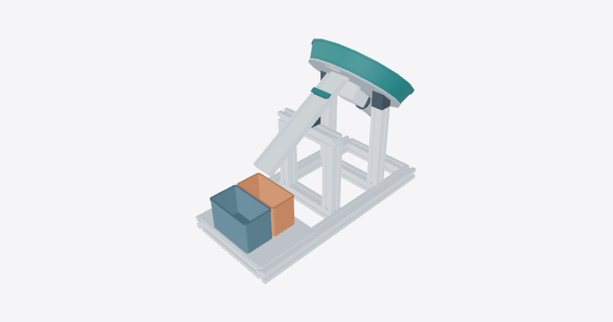
Lay the two base runners parallel on a flat surface. Fit the front tie and rear tie between their ends. Fit the slide tower tie at mid-frame and the drum tower tie between it and the rear tie. Square the base by comparing its two corner-to-corner diagonals before securing the joints.
Assemble the hopper tower
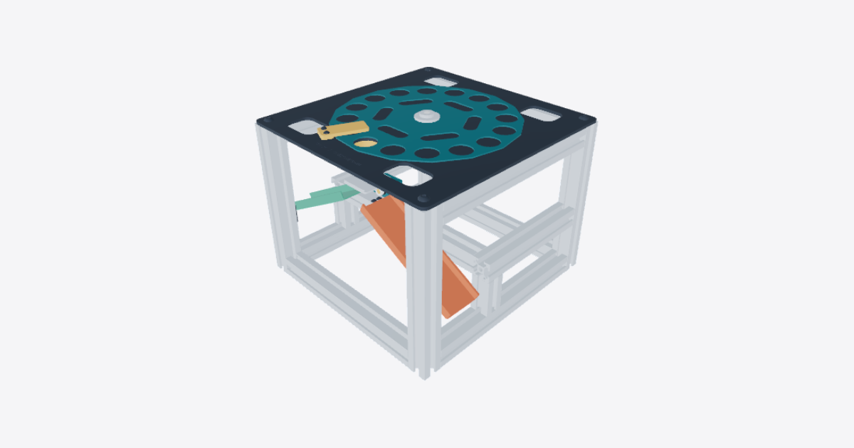
Fit the two hopper uprights to the drum tower tie, one near each end. Seat the two hopper angle shoes on the matching uprights. Orient the two sloped faces in the same direction and check that they lie in the same plane.
Seat the 40° hopper backing plate
Set the ported backing plate on both hopper angle shoes at 40° to the base. Face the bowl side up and orient the off-center discharge opening toward the slide tower. Check that the plate sits on both shoes without rocking.
Mount the 12 V worm gearmotor
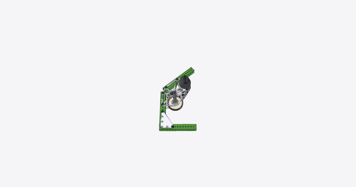
With the power disconnected, bring the assembled 12 V worm gearmotor up to the underside of the backing plate. Align its output spindle with the center opening and seat the reducer housing against the plate, with the motor can extending toward the rear. Secure the drive mechanically and leave the terminals disconnected.
Fit the metering wheel and clamp boss
From the bowl side, align the twelve-pocket metering wheel with the output spindle and seat it above the backing plate. Fit the carrier clamp boss at the center after the wheel is seated. Keep the plate’s discharge opening unobstructed.
Fit the flared feed bowl
Lower the flared feed bowl over the metering wheel and seat its rim against the hopper backing plate. Before moving on, check that the bowl is seated evenly and does not contact the metering wheel.
Build the ramp support
Fit the two slide uprights to the slide tower tie. Seat the slide bearer across their tops and center the slide angle shoe on it, with the shoe sloping down toward the catch-bin end.
Set the magnet ramp at 32°
Before fitting the magnet slide ramp, check that all ten magnets are seated flush in the channel pockets and that the doctor gate spans the channel near its upper end. Seat the ramp on the slide angle shoe at 32° to the base. Center its high end under the hopper discharge opening and point the low end toward the bin shelf position.
Place the bin shelf
Set the bin shelf across the base runners at the front tie, below the ramp outlet. Check that it sits flat and does not rock.
Place both catch bins and check alignment
Set the Cu near receiver directly below the ramp outlet. Set the Zn far receiver just beyond it, toward the front tie. Center both bins across the ramp and check that each lifts out without disturbing the other.
With power still disconnected, check that the hopper port feeds onto the ramp, the ramp points toward the bins, and the frame and mounts are secure.