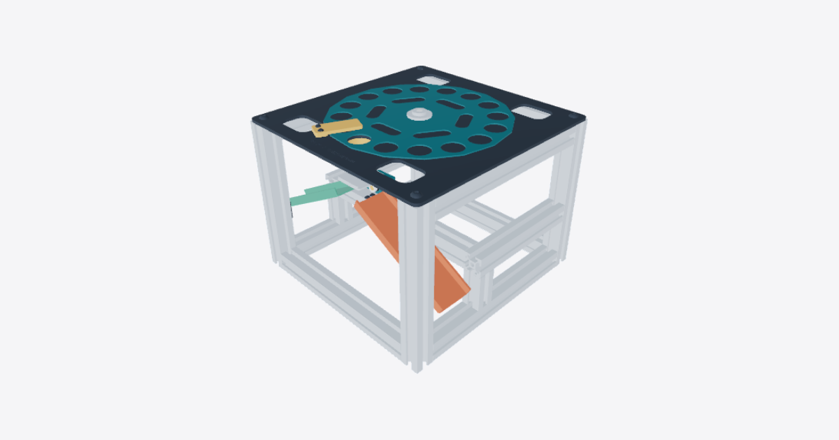
Step-by-step assembly of the 2020 frame
11 steps
Lay out the 2020 frame base
Lay out the two lower side rails and two lower transverse rails on a flat surface. Match the side and end positions shown in the 3D view. Keep the joints loose enough to square the frame after the uprights are in place.
Fit the uprights and upper rails
Join the four uprights to the corners of the base. Fit the two upper side rails and the single upper transverse rail on the side shown. Check that the base is square and the four upright tops are in the same plane before securing the frame joints.
Build the weighing-head support
Fit the two bearer supports between the lower side rails and the two sensor bearers. Fit the weighing-head cross rail between the bearers at the offset position shown. Keep its top face level so both isolation mounts can seat evenly.
Install the isolated load-cell beam
Seat the two elastomer bobbins on the weighing-head cross rail. Set the isolated anchor plate on them and secure it with the two isolation mount screws. Fasten the fixed end of the 100 g load-cell beam to the plate with the two anchor bolts. Orient the free end toward the drop opening. Check that the free end does not touch the frame.
Fit the servo cradle and servo
Fasten the live-end servo cradle to the free end of the load-cell beam with the two live-end bolts. Fit the two servo pillars and seat the micro servo on the cradle with its output facing the pan. Secure it with the two servo clamps. Keep the load-cell beam supported at its fixed end and avoid pressing on its free end.
Install the stationary deck
Set the stationary coin track and deck on the four uprights. Orient the offset drop opening toward the servo output side, where the weigh pan will sit. Align the corner holes and install the four deck fixings. Check that the deck sits flat without rocking.
Fit the gearmotor and the 15 mm drop chute
Hold the gearmotor against the underside of the deck with its D-flat output spindle through the center opening. Secure the flange with the two flange screws. Seat the 15 mm drop tube under the offset opening before fitting the crank and pan.
Mount the tilting weigh pan
Work through the open side of the frame below the deck. Fit the tipping crank to the servo output and position the bidirectional weigh pan on the crank. In the neutral position, the receiving face should be level and centered below the drop tube without touching it. Do not force the servo output to move by hand.
Seat the 180 mm, 16-pocket carrier wheel
Place the 16-pocket carrier wheel over the center opening on the stationary track. Align the flat of the keyed drive hub with the flat on the spindle and seat the hub in the carrier center as shown. Check that the wheel sits flat and that a pocket lines up with the drop opening when indexed to that position.
Fit the metering blade
Position the single-layer metering blade beside the drop opening, with its working edge over the pocket path as shown. Fit the two wiper clamps. Check that the blade does not rub the carrier and that a single coin can pass beneath it.
Install the accept and reject exit chutes
Fit the accept outfeed hanger and reject outfeed hanger on opposite sides of the frame as shown. Set the accept slide and reject slide on their matching sides, with the high ends facing the pan and the low ends leading out of the frame. Check that both inlets clear the neutral pan and that neither chute touches the load-cell beam or its cradle. Keep the unit unpowered during these fit checks.