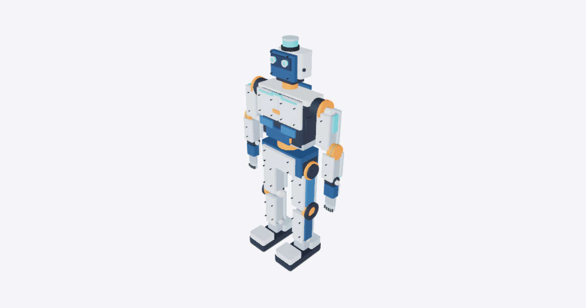
展示从零倒一怎么一步一步组装 Take the HRX01
18 steps
Secure the robot and isolate power
Support the complete robot so the torso, pelvis and limbs cannot fall or rotate as connections are released. Shut the robot down, disconnect external power and charging connections, and set the power isolator switch to OFF. Prevent reconnection throughout disassembly. Keep hands clear of unsupported joints.
Remove the back-panel fasteners
Support the rear panel. Unscrew and retain the four back-panel retaining fasteners, keeping them together for reassembly. Do not disturb internal electrical connections.
Remove the rear access obstructions
Release and remove the back connector cover. Release the battery pull handle from its attachment and move it clear of the back panel. Retain both items with their attachments. Do not disturb the battery connector or pull on internal wiring.
Remove the back panel
Support the removable back panel. Disengage its remaining retention and withdraw the panel toward the rear, clear of the torso and internal wiring. Place the panel aside.
Disconnect and withdraw the battery
Support the removable battery pack directly. Release its retention and disengage the battery connector without pulling on wires. Withdraw the pack toward the rear. Protect the exposed terminals and place the battery away from the work area. Do not open the battery enclosure.
Remove the chest fasteners and central indicator
Support both chest panels. Unscrew the eight chest-panel retaining fasteners, four on each side. Keep left-side and right-side hardware separate. Release the torso status indicator at the panel seam, disconnect its lead and lift it forward clear of the panels.
Remove the left and right chest panels
Support the two detachable chest panels and both chest light bars. Disconnect the light-bar leads. Disengage the panels and bring them forward with their light bars, clear of the torso. Leave the internal ribs and vents in place.
Release the arm electrical connections
Label the left and right arm connections. Release the two wrist data connectors by their connector bodies. Free the two shoulder cable conduits and their associated leads from the arm interfaces. Secure the disconnected wiring clear of the shoulder joints; do not pull on cables or cut the conduits.
Remove the complete head and neck module
Support the head and neck module independently. Disconnect the head wiring at the torso interface and release the neck-to-torso mounting retention. Lift the complete module upward clear of the torso and place it on a protected surface. Keep the cameras, lidar and head shells assembled.
Remove the left arm module
Support the left arm module at the shoulder and forearm. Release its shoulder-to-torso mounting retention. Confirm the wiring is free, then move the complete arm clear of the torso and place it on a protected surface. Keep the shoulder, elbow, wrist and hand assembled.
Remove the right arm module
Support the right arm module at the shoulder and forearm. Release its shoulder-to-torso mounting retention. Confirm the wiring is free, then move the complete arm clear of the torso and place it on a protected surface. Keep the shoulder, elbow, wrist and hand assembled.
Remove the pelvis-cover fasteners
Keep the pelvis and both legs supported independently. Unscrew and retain the four pelvis-cover retaining fasteners. Do not release a load-bearing hip connection while a leg is unsupported.
Remove the pelvis covers
Remove the pelvis front cover toward the front and the pelvis rear cover toward the rear. Release any remaining cover attachments without levering against the hip joints. Keep the covers and their hardware together.
Release the leg electrical connections
Label and release both leg data connectors. Free both knee signal conduits and their leads from the leg interfaces. Disconnect the leg leads routed through both hip cable conduits, leaving the hip conduits on the pelvis. Secure all loose wiring clear of the hip mounts and withdrawal paths.
Remove the left leg with its hip mount
Support the left leg module along its length. Release the pelvis-side retention of the left hip mount yoke and left hip reinforcement plate. Keep the yoke and plate with the leg as it is moved outward to the left, clear of the pelvis. Keep the knee, ankle and foot assembled.
Remove the right leg with its hip mount
Support the right leg module along its length. Release the pelvis-side retention of the right hip mount yoke and right hip reinforcement plate. Keep the yoke and plate with the leg as it is moved outward to the right, clear of the pelvis. Keep the knee, ankle and foot assembled.
Separate the torso module from the pelvis
Support the torso module and its installed electronics independently of the pelvis. Disconnect wiring crossing the waist interface and release the torso-to-waist mounting retention. Lift the torso upward clear of the waist assembly, keeping the installed electronics with it. Place the module on a protected support. Leave the waist shaft, reducer housing and bearing with the pelvis.
Secure and inspect the separated modules
Secure the remaining pelvis assembly on a stable surface. Account for the battery, head, both arms, both legs, torso, removed panels and retained hardware. Protect exposed connectors and terminals. Check for trapped wiring, damaged mounting faces and loose hardware. Keep each module assembled internally and identify its mating connections for reassembly.