1. Prepare the main body and stand
Tools
- Utility knife
- 2.5 mm ball-end Allen key
Caution: Cut carefully with a utility knife, not a scalpel.
10 steps
Print the parts and review the intended use
The OpenFlexure microscope is for research, teaching and schools. Building it from the open design does not make it a certified medical device, and any diagnosis must be done by qualified professionals.
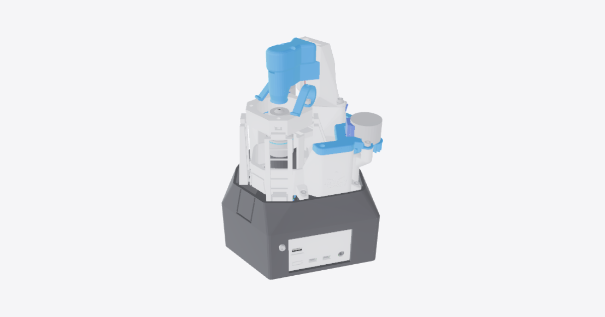
This is the first stage of building the OpenFlexure Microscope v7 high-resolution version.
Credit: OpenFlexure Microscope v7.0.0-beta5 by the OpenFlexure Project (Richard Bowman et al.), licensed CERN-OHL-S-2.0. Source and official build guide: openflexure.org and build.openflexure.org/openflexure-microscope/v7.0.0-beta5. Adapted by TwinWorks; not endorsed by the OpenFlexure Project.
Print all parts before starting assembly. Print the optics module in black and the condenser in a dark opaque filament. For this stage, prepare only the main body, stand and 16 M3 nuts: 12 for the main body and 4 for the stand. Keep the main body and stand separate throughout this procedure.
Remove the brims
Peel the brims carefully from the main body and stand using a utility knife, not a scalpel. Cut the main body's custom brim free before peeling it away. Support the print and keep your fingers out of the blade's path.
Cut the main body's printing ties
Use the utility knife to cut the 6 ties inside the actuator columns of the main body and the 4 ties on its rear legs. Trim all 10 ties flush. Cut only the temporary ties, leaving the surrounding printed structure intact.
Embed the 4 stage nuts
Place the 4 M3 nuts in the stage side slots of the main body, one nut per slot. For each nut, pass a temporary M3x10 screw through the corresponding hole and engage the nut. Use a 2.5 mm ball-end Allen key to tighten the screw gradually, pulling the nut into its recess. Stop when the nut is seated, then unscrew and remove the temporary screw. Repeat for all 4 nuts.
Embed the 2 illumination-platform nuts
Place the 2 M3 nuts in the two nut recesses of the main body's illumination platform. Leave the third hole without a nut. Pull each nut into its recess with a temporary M3x10 screw and a 2.5 mm ball-end Allen key. Stop when seated, then remove the temporary screw.
Embed the 2 X motor-mount nuts
Place the 2 M3 nuts in the X motor-mount recesses of the main body. Pull each nut into its recess with a temporary M3x10 screw and a 2.5 mm ball-end Allen key. Stop when seated, then remove the temporary screw. Do not fit the motor during this stage.
Embed the 2 Y motor-mount nuts
Place the 2 M3 nuts in the Y motor-mount recesses of the main body. Pull each nut into its recess with a temporary M3x10 screw and a 2.5 mm ball-end Allen key. Stop when seated, then remove the temporary screw. Do not fit the motor during this stage.
Embed the 2 Z motor-mount nuts
Place the 2 M3 nuts in the Z motor-mount recesses of the main body. Pull each nut into its recess with a temporary M3x10 screw and a 2.5 mm ball-end Allen key. Stop when seated, then remove the temporary screw. Check that the main body now contains 12 nuts: 4 at the stage, 2 at the illumination platform and 2 at each of the X, Y and Z motor mounts.
Remove the stand's printing supports
Rock the printing supports back and forth to break them away from the stand. Remove the detached material and clear the mounting-lug nut recesses without damaging the lugs.
Embed the 4 stand nuts
Place the 4 M3 nuts under the mounting lugs of the stand, one nut per lug. Pull each nut into its recess using a temporary M3x10 screw and a 2.5 mm ball-end Allen key. Stop when seated, then remove the temporary screw.
Check that all 4 nuts are retained and the lugs are undamaged. The main body and stand are now prepared, with 16 embedded nuts in total. Keep them separate for the next assembly stage.