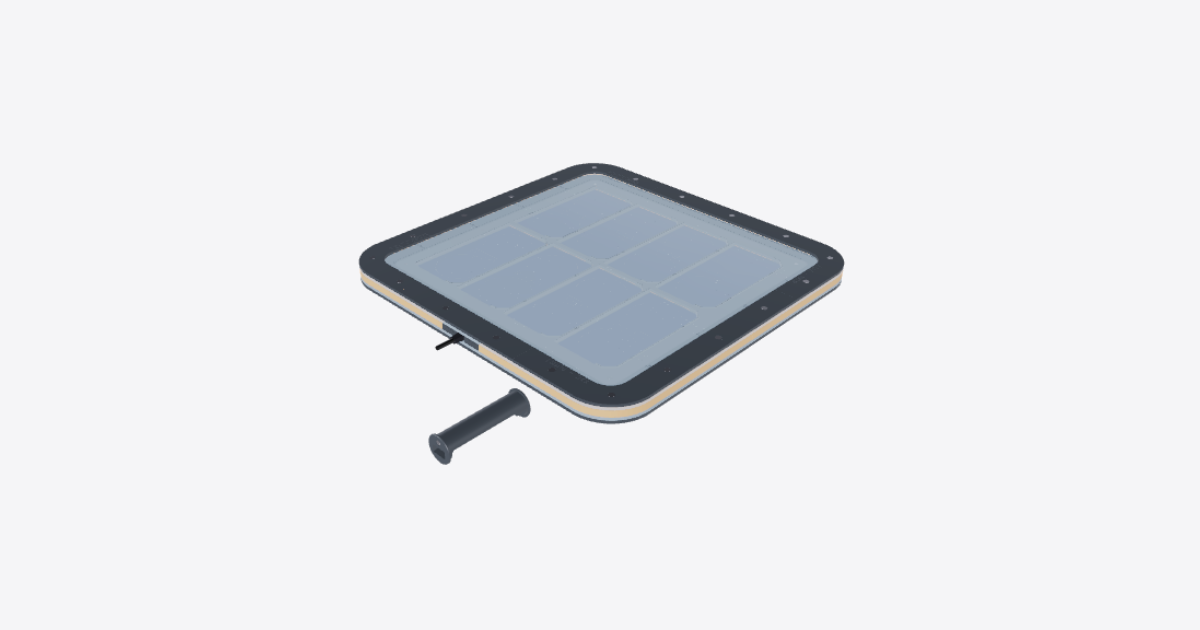
1. Build the solar panel
Tools
- hammer
- Cutting tool
- Soldering iron
- Multimeter
- Cable cutter
- Wire stripper
- PH1 screwdriver
- 2.5 mm Allen key
Protective equipment
- latex gloves
Notice: Solar cells are very fragile. Handle them gently.
Notice: Power output may be lower than expected.
17 steps
Prepare the panel parts and remove the protective foil
Build only the solar panel. Follow the Biosphere Solar DEV KIT How-To, DEV KIT by Biosphere Solar BV, (c) 2024 Biosphere Solar, CERN-OHL-S-2.0. Part numbers are shown in brackets.
Wear latex gloves. Handle the solar cells gently: they are very fragile. Remove the protective foil from both PMMA sheets [1A, 1B].
Credit: DEV KIT by Biosphere Solar BV, (c) 2024 Biosphere Solar, licensed CERN-OHL-S-2.0. Source files and How-To: wikifactory.com/@biosphere-solar/dev-kit. Adapted by TwinWorks: the 3D model was assembled from the published parts, and the cells, seals, bolts, nuts and cable are simple stand-ins.
Arrange the bottom edge strips
Arrange the three bottom edge strips [11A] and the single bottom edge strip [11B] in their panel positions, with the square nut cut-outs facing down.
Press the M3 nuts into the bottom strips
Press the twenty nuts (M3) into the square cut-outs in the bottom edge strips [11A x3, 11B x1], with the nuts facing down. If the cut-outs are tight, use a hammer to seat the nuts.
Lay the bottom sheet on the strips
Lay the bottom sheet [1A] on the bottom edge strips. Keep the engraved stick seal between these lines side facing up and align the holes.
Apply the bottom EPDM seal
Stick the EPDM seal [2] onto the bottom sheet [1A], between the engraved lines. Cut the ends at 45 degrees and overlap them slightly.
Position the MDF cell template
Place the MDF cell template [3] on the engraved lines of the bottom sheet. Align OUTPUT with the template cut-out.
Place the cell beds and branding piece
Place the eight cell beds [5] and the branding piece [14] into their openings in the template.
Solder, test and place the eight cells
Wear latex gloves and handle the eight half-cut solar cells gently. Cut the dogbones in half and solder them to the cells using solder wire.
Measure each cell: it must read 0.2 to 0.6 V, with polarity matching the template's + and - marks. Place the tested cells in the cell beds, following those polarity marks.
Connect and test the cell string
Solder together the overlapping middle dogbones between the eight solar cells. Add tabbing wire at the template markings. Measure the complete string: it should read approximately 4 V.
Prepare and solder the output cable
Cut the cable to 0.5 to 1 m and strip the conductors. Solder the blue conductor to + and the brown conductor to - at the cell-string output.
Place the cell holder sheet
Place the cell holder sheet [9] over the template with its countersinks facing up. Align its four corner holes with the template.
Fasten the cell holder with the corner screws
Fix the cell holder sheet [9] to the template using the four small corner screws. Use a PH1 screwdriver.
Position the cork spacers
Align the four cork spacers [4A x2, 4B x2] with the holes in the bottom sheet [1A]. Leave the output-edge gap open for the cable-through piece [10A].
Fit the cable-through piece and TPU insert
Put the TPU insert [10B] into the cable-through piece [10A]. Run the cable through the insert and position the cable-through piece in the gap between the cork spacers, with the text facing up.
Seal and fit the top sheet
Apply the EPDM seal [2] to the top sheet [1B] between the engraved lines. Cut the ends at 45 degrees and overlap them slightly, as for the bottom sheet.
Lay the top sheet seal-down, aligning the holes. Sandwich the cable between the two seals at the cable exit.
Lay on the top edge strips
Lay the four top edge strips [11C] on the top sheet. Keep the countersinks facing up and align all bolt holes.
Fasten the panel with the 20 M3x18 bolts
Fit the twenty bolts (M3x18) through the top edge strips into the captive M3 nuts. Use a 2.5 mm Allen key and work around the panel, starting from one edge or corner.
Note: power output may be lower than expected.