
1 Build one half
Notice: Never plug or unplug the TRRS cable while USB is connected.
10 steps
Check the parts
Corne keyboard by foostan, github.com/foostan/crkbd. Licence: CC BY 4.0 / MIT. 3D model assembled by TwinWorks from the published case, board and plate files. This guide is not official Corne documentation.
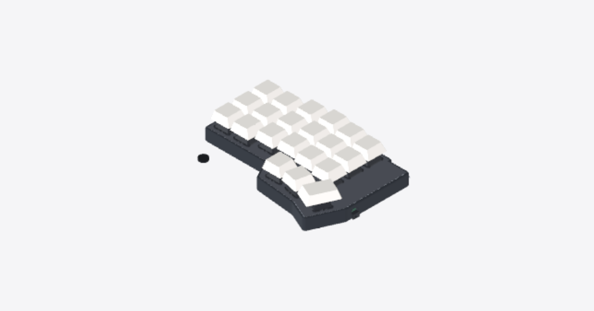
Prepare the parts for one Corne v4 half, Cherry MX, hot-swap. Match the parts to the left half shown in the 3D view:
- One board with all 21 hot-swap sockets already fitted.
- One switch plate and one case.
- All 21 switches and all 21 keycaps, including one 1.5u thumb keycap.
- Four M2 spacers, 7.5 mm long.
- Eight M2 x 5 mm screws: four case screws and four plate screws.
- Four rubber feet.
Keep USB and the TRRS cable disconnected during assembly.
Snap the switches into the switch plate
Orient the switch plate to match the board outline. Align all 21 switches with the plate openings and the socket positions on the board.
Press each switch squarely into its opening until both retaining clips engage. Check that every switch sits flush in the plate and that no clip remains above it.
Press the switches into the board
Check that every switch pin is straight. Align the switch plate and all 21 switches over the board so every pin lines up with its hot-swap socket.
Support the board close to the socket being fitted. Press the plate and switches down evenly, working across the board without bending it, until every switch is fully seated. If a switch resists, stop and realign its pins instead of forcing it.
Check underneath that no pin has folded beside a socket and no socket has lifted from the board.
Screw the spacers to the case
Place the four M2 spacers, 7.5 mm long, over the mounting holes inside the case.
Insert four M2 x 5 mm case screws from below. Hold each spacer while starting its screw, then tighten gently until the spacer sits securely against the case. Do not overtighten.
Lower the board and plate onto the spacers
Lower the board, switch plate and all 21 switches together into the case. Align the four plate mounting holes with all four spacers.
Keep the assembly level and guide the USB connector and TRRS jack into their case openings without forcing them. Let the plate rest on all four spacers.
Fit the four plate screws
Fit the four M2 x 5 mm plate screws through the switch plate into all four spacers. Start all four screws before tightening them.
Tighten a little at a time across opposite corners until the plate is secure and sits evenly. Stop when the screws are snug; do not bend the plate or overtighten.
Stick on the rubber feet
Support the half and turn it over. Make sure the four rubber-foot positions on the underside of the case are clean and dry.
Peel the backing from the four rubber feet and press them firmly into the positions shown. Turn the half upright and check that all four feet contact a flat surface without rocking.
Fit the keycaps
Fit all 21 keycaps onto the switch stems, following the positions shown in the 3D view. Put the 1.5u keycap on the outer thumb-cluster switch.
Align each stem and press straight down. Check that adjacent keycaps do not touch and that each key moves freely and returns when released.
Check the completed half
With both cables still disconnected, inspect the completed half:
- The board and switch plate sit evenly in the case.
- All eight screws are fitted and snug.
- All 21 switches are clipped in and fully seated in their sockets.
- All keycaps are secure, including the 1.5u thumb keycap, and every key moves freely.
- All four rubber feet are secure and the half does not rock on a flat surface.
- The USB connector and TRRS jack are accessible and not pressed against the case.
- No loose screw or other loose item remains inside.
Build the second half the same way
Repeat steps 1 to 9 with the matching parts for the second half. Follow the same order and use its mirrored board, switch plate and case. Keep the 1.5u keycap on its thumb cluster.
Keep USB disconnected whenever connecting or disconnecting the TRRS cable. Never plug or unplug the TRRS cable while USB is connected.