
TwinWorks
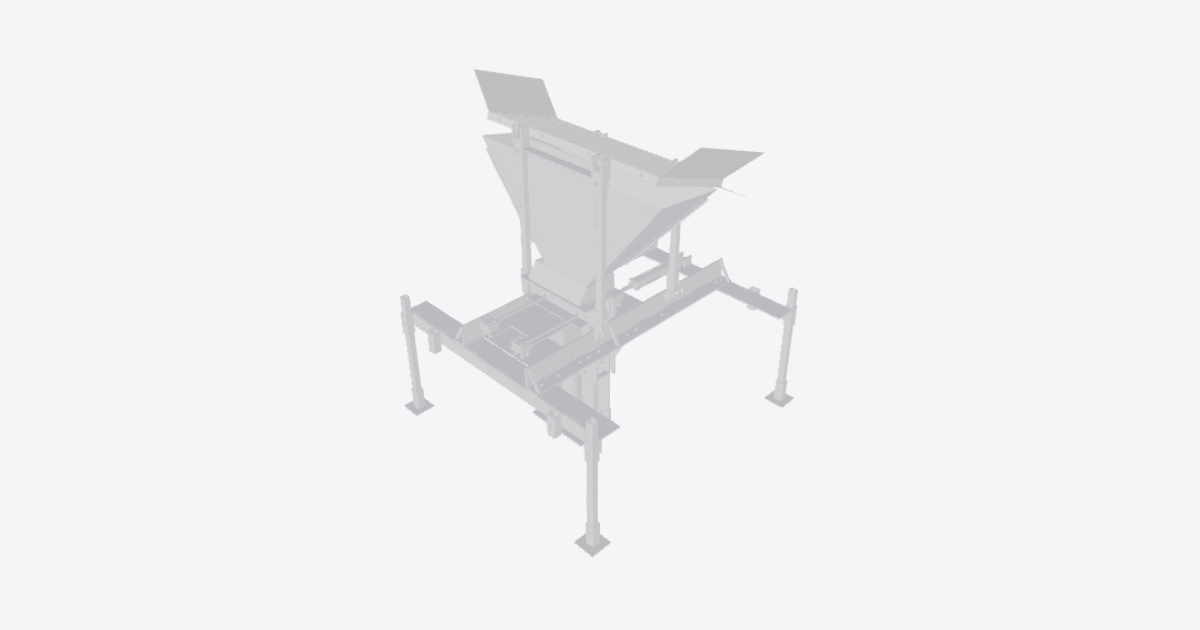
Earth-block press (Open Source Ecology CEB) – 3D model preview

Earth-block press (Open Source Ecology CEB)

Téa · Construction · 3D model · Updated 6 Nov 2026

Open in 3D

  • Procedures3shared publicly
  • Views0all time
  • Rating–No ratings yet
  • Likes0from the Community

0 comments

Procedures

1. Frame, drawer and main cylinder

Assembly · 8 steps · No ratings yet

Protective equipment

  • Welding and grinding PPE
8 steps
  1. Prepare the first-stage assembly

    Build the frame, drawer and main cylinder as the first stage of the Open Source Ecology Compressed Earth Block press v17.08.

    Wear welding and grinding PPE for the applicable work. Arrange stable support for the frame before turning or assembling it. Keep hands clear of unsupported parts.

    This stage uses only the Frame, Drawer and main Cylinder sub-assemblies.

    Credit: CEB Press v17.08 by Open Source Ecology (wiki.opensourceecology.org/wiki/CEB_Press_v17.08), CAD assembly by Emmanouil Polemidis, licensed CC BY-SA 4.0 (creativecommons.org/licenses/by-sa/4.0). Build notes from the OSE fabrication decks. Adapted by TwinWorks; this guide is shared under the same licence.

  2. Bolt the frame plates and support the frame upside down

    Bolt the frame plates together to form the Frame sub-assembly. Stand the frame upside down on stable support and secure it against tipping.

    Tighten the top and bottom bolts. Leave the middle plate bolts loose for the wear plate and cylinder alignment.

  3. Fit the wear plate

    Fit the wear (AR) plate under the middle frame plates of the Frame sub-assembly. Keep the middle plate bolts loose while positioning the wear plate.

  4. Grind sharp corners and weld spatter

    On the Frame sub-assembly, grind all sharp corners and weld spatter flat. Keep the frame securely supported throughout grinding.

  5. Slide the drawer into the frame

    Support the Drawer sub-assembly and slide it into the Frame sub-assembly. Position its pressing surface under the main cylinder mounting position. Keep hands clear of the sliding interfaces.

  6. Set drawer height and finish the pressing surface

    Check and adjust the height of the Drawer sub-assembly to within 1/32 inch. Grind its pressing surface flat.

    Check that the drawer slides without binding and that its pressing surface remains under the main cylinder mounting position.

  7. Place and attach the main cylinder with its spacers

    Support the main Cylinder sub-assembly with its spacers and place it in the Frame sub-assembly. Align the mounting interfaces and attach the cylinder.

    Keep the middle frame plate bolts loose until the cylinder and spacers are seated. Do not release the cylinder support until its attachment is secure.

  8. Fully tighten the frame bolts and check the chamber

    With the main Cylinder sub-assembly attached and its spacers seated, fully tighten all frame bolts on the Frame sub-assembly, including the middle plate bolts.

    Check that the Drawer sub-assembly slides without binding and that its pressing surface is flat and correctly positioned beneath the main cylinder. Check that the compression chamber is 12 × 6 inches.

    Bolt torques and welding details are specified in the OSE fabrication decks, not in this guide.

2. Arms, hopper and secondary cylinder

Assembly · 6 steps · No ratings yet

Tools

  • Lifting aid

Protective equipment

  • Welding and grinding PPE

Warning: Support heavy steel parts with a helper or lifting aid.

6 steps
  1. Prepare for the second assembly stage

    Begin after the frame, drawer and main cylinder have been assembled. Keep the press unpowered and support it securely on a level surface.

    Stage the arms, secondary cylinder, hopper seat, Crate and hopper as complete sub-assemblies. Work with a helper or a lifting aid for heavy steel parts. Wear welding and grinding PPE for those activities; this procedure does not call for additional welding or grinding.

    Follow the installed positions shown in the model. The separated positions illustrate staging, not a prescribed lifting or insertion path. Use the OSE decks for bolt sizes and tightening torques.

    CEB Press v17.08 by Open Source Ecology; CAD assembly by Emmanouil Polemidis; CC BY-SA 4.0. CEB Press v17.08

  2. Fit the arms to the frame

    Support the arms sub-assembly with a helper or lifting aid. Orient the complete assembly around the frame as shown in the installed model position.

    Bring the mating mounting points into alignment without forcing them. Fit and secure the mounting hardware before releasing the support. Use the OSE decks for bolt sizes and tightening torques.

  3. Mount the secondary cylinder

    Support the secondary cylinder sub-assembly and orient it alongside the drawer as shown in the installed model position. This cylinder moves the drawer.

    Align both cylinder attachment points with their mating mounts and secure the attachment hardware. Keep the drawer supported and keep fingers out of the joints while aligning the connections. Do not energize the hydraulic system during fitting. Use the OSE decks for attachment hardware specifications and tightening torques.

  4. Fit the hopper seat

    Support the hopper seat sub-assembly and position it on the frame at the location shown in the installed model position.

    Align its mounting holes with the mating holes. Seat the assembly fully and secure its mounting hardware before removing the support. Use the OSE decks for bolt sizes and tightening torques.

  5. Fit the Crate sub-assembly

    With a helper or lifting aid, raise and position the complete Crate sub-assembly above the installed hopper seat, matching the orientation and mounting locations shown in the model.

    Keep it supported while aligning and securing its mounting connections. Ensure the assembly is stable before releasing the lifting support. Use the OSE decks for bolt sizes and tightening torques.

  6. Fit the hopper and inspect the assembly

    With a helper or lifting aid, lift the complete hopper sub-assembly into its upper position within the supporting structure, matching the installed model orientation. Align the lower outlet with the feed opening beneath it.

    Keep the hopper supported while aligning and securing its mounting connections. Use the OSE decks for bolt sizes and tightening torques. Release the lifting support only after the hopper is secure.

    With the press still unpowered, inspect the five installed sub-assemblies. Confirm that their positions match the model, all mounting connections are secured, and no loose hardware or lifting equipment remains in the drawer path. Leave the hydraulic system unpowered at the end of this assembly procedure.

3. Hydraulics and controls

Assembly · 9 steps · No ratings yet

Warning: Never disconnect a hydraulic hose or reach into the press while the system is under pressure; switch off the Power Cube and release pressure first.

9 steps
  1. Isolate the press before hydraulic assembly

    This is the third assembly stage for the Open Source Ecology Compressed Earth Block press v17.08: hydraulics and controls.

    Switch off the Power Cube and release hydraulic pressure before starting work. Never disconnect a hydraulic hose or reach into the press while the system is under pressure.

    Locate the highlighted main cylinder and secondary cylinder. Leave both installed while fitting the hydraulic connections.

    Build-deck attribution supplied for this procedure: CEB Press v17.08 Hydraulics + Controls, Open Source Ecology, CC BY-SA 4.0.

  2. Fit the two control valves with hydraulic fittings

    Keep the hydraulic system isolated and depressurized. Fit the hydraulic fittings to the two control valves, using the following quantities in total across the pair:

    • 8 swivel fittings, 1/2 to 3/4 inch NPT.
    • 4 nipples, 3/4 inch.
    • 4 elbows, 3/4 inch.
    • 1 tee, 3/4 inch.
    • 1 reducer, 3/4 to 1/4 inch, for the pressure switch.

    Keep dirt out of all open connections. Match each fitting to its intended valve connection before tightening; do not force mismatched threads.

    The highlighted main cylinder and secondary cylinder identify the actuators served by the valves. The valves and fittings are not represented in the 3D view.

  3. Prepare the Power Cube supply hoses

    Prepare the supply hoses from the Power Cube hydraulic power unit using 10 foot, 3/4 inch hoses. Keep the Power Cube switched off and the circuit depressurized while assembling connections.

    Check that the hoses and fittings are suitable for the Power Cube bypass-pressure range of 1500 to 3000 psi. Keep hose ends clean and protected until connection.

    Lay out the hoses toward the control-valve location without twisting them or placing them across sharp edges or moving parts. The highlighted main cylinder and secondary cylinder provide press-side orientation; the hoses and Power Cube are not shown.

  4. Fit the secondary-cylinder elbows

    Locate the highlighted secondary cylinder, the smaller horizontal cylinder beside the press mechanism.

    With the hydraulic system depressurized, fit SAE 12 to 3/4 inch NPT elbows to its hydraulic connections. Orient the elbows downward. Keep the connections clean and leave room for the hoses to curve without kinking or rubbing against the surrounding structure.

    Leave the cylinder installed in its existing position.

  5. Fit the main-cylinder elbows

    Locate the highlighted main cylinder, the large vertical cylinder below the pressing assembly.

    With the hydraulic system depressurized, fit SAE 12 to 3/4 inch NPT elbows to its hydraulic connections. Orient the elbows downward. Keep the connections clean and provide clearance for the hoses around the cylinder and frame.

    Leave the cylinder installed in its existing position.

  6. Install the pressure switch and prepare control wiring

    Keep the Power Cube switched off and the hydraulic system depressurized. Isolate power to the controller before wiring.

    Fit the pressure switch at the 3/4 to 1/4 inch reducer provided in the valve fittings. Attach the pressure switch to the controller and prepare the CAT5 control wiring. Match terminals to their identified functions before making electrical connections.

    Route the control cable away from pinch points, sharp edges and moving parts, and support it so cable tension is not carried by the terminals.

    The highlighted main cylinder and secondary cylinder identify the controlled actuators; the switch, controller and wiring are not represented by these highlights.

  7. Mount both control valves

    Mount both control valves on a 1/4 inch steel plate hung from a stake. Secure the plate and valves so they cannot shift or pull on the hydraulic connections.

    Position the assembly so the controls are accessible without reaching into the press. Allow clearance for hose bends and protect the control wiring from strain.

    Use the highlighted main cylinder and secondary cylinder as references when arranging the valve assembly and hose runs. The valve mounting plate and stake are not shown in this view.

  8. Route the cylinder hoses and complete identified connections

    Keep the Power Cube switched off and release hydraulic pressure before handling any hose connection.

    Route the hoses between the control valves and the downward-facing elbows on the highlighted main cylinder and secondary cylinder. Keep the hoses clear of the drawer, arms and other moving parts. Leave sufficient slack for movement without stretching, kinking or rubbing.

    Connect only hose ends whose supply, return and cylinder-port assignments have been positively identified. Do not choose port assignments by physical proximity. Secure the hose runs without loading the fittings.

  9. Inspect the assembly without applying pressure

    With the Power Cube switched off, hydraulic pressure released and controller power isolated, inspect the completed work:

    • Both control valves are secure on the 1/4 inch steel plate and stake.
    • The hydraulic fittings are seated and the cylinder elbows face downward.
    • Supply and cylinder hose connections are identified and secure.
    • Hoses at the main cylinder and secondary cylinder have clearance from moving parts, sharp edges and pinch points.
    • The pressure switch is fitted and the CAT5 wiring is supported, with identified terminal connections.

    Leave the Power Cube switched off and the controller isolated at the end of this assembly stage. Do not energize an incompletely connected or unidentified hydraulic or control circuit.