
TwinWorks
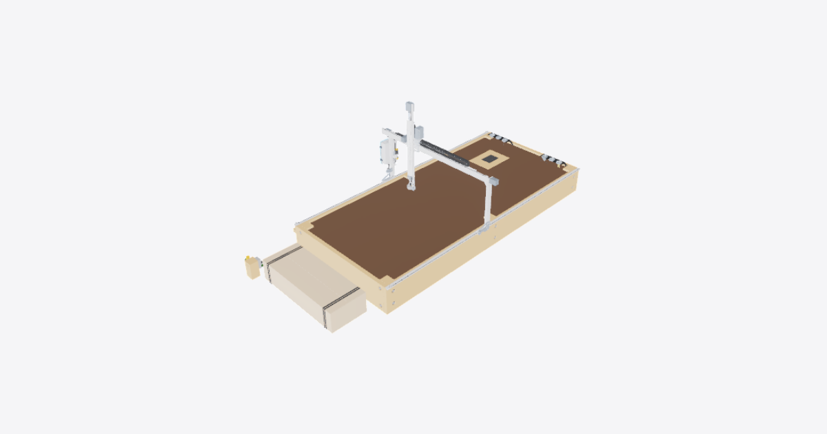
FarmBot garden robot – 3D model preview

FarmBot garden robot

Téa · Agriculture · 3D model · Updated 6 Nov 2026

Open in 3D

  • Procedures5shared publicly
  • Views0all time
  • Rating–No ratings yet
  • Likes0from the Community

0 comments

Procedures

1. Tracks

Assembly · 8 steps · No ratings yet

Tools

  • T25 driver
  • 150 grit sandpaper
8 steps
  1. Tracks: lay out the first track

    Lay out the three 1 m track extrusions end to end along the top of the first long side of the raised bed.

    While the ends are accessible, position the two 40 mm nut bars, one at each joint. Slide each bar halfway into one extrusion, then fit the neighbouring extrusion over the projecting half so that 20 mm sits inside each extrusion. Bring the ends together and align the V-faces. Keep each extrusion flush with the side and the top of the bed.

    Credit: based on the official FarmBot Genesis v1.8 assembly guide (genesis.farm.bot). FarmBot Genesis CAD by FarmBot Inc., released under CC0 1.0.

  2. Tracks: secure the first track to the bed

    Use the nine wood screws to secure the first track, three screws through the mounting holes in each extrusion. Drive them with a T25 driver, keeping the extrusions flush with the side and the top of the bed and the adjoining V-faces aligned.

  3. Tracks: lock the first track joints

    Fit and tighten the four M5x4 set screws into the two 40 mm nut bars, two screws per joint with one on each side of the joint. Keep each nut bar centred, with 20 mm inside each neighbouring extrusion, and hold the V-faces aligned as you lock the joints.

  4. Tracks: lay out the second track

    Lay out the remaining three 1 m track extrusions end to end along the top of the opposite long side of the raised bed.

    While the ends are accessible, position the two 40 mm nut bars, one at each joint. Slide each bar halfway into one extrusion, then fit the neighbouring extrusion over the projecting half so that 20 mm sits inside each extrusion. Bring the ends together and align the V-faces. Keep each extrusion flush with the side and the top of the bed. Keep the second track parallel to the first along its full length, within about 1 cm.

  5. Tracks: secure the second track to the bed

    Use the remaining nine wood screws to secure the second track, three screws through the mounting holes in each extrusion. Drive them with a T25 driver, keeping the extrusions flush with the side and the top of the bed and the adjoining V-faces aligned. Maintain parallelism with the first track along the full length, within about 1 cm.

  6. Tracks: lock the second track joints

    Fit and tighten the remaining four M5x4 set screws into the two 40 mm nut bars, two screws per joint with one on each side of the joint. Keep each nut bar centred, with 20 mm inside each neighbouring extrusion, and hold the V-faces aligned as you lock the joints.

  7. Tracks: check parallelism and mounting

    Check that the six track extrusions form two tracks that remain parallel within about 1 cm along their whole length. Compare the distance between corresponding V-faces at both ends, at each joint and between the joints.

    Check that all six extrusions are flush with the side and the top of the bed, with three wood screws per extrusion. Check that all four joints have a centred 40 mm nut bar and two tightened M5x4 set screws, one on each side.

  8. Tracks: smooth the V-faces at every joint

    Gently run a finger along the V-faces of the six track extrusions, checking all four joints for bumps. Sand any raised edges at the joints with 150 grit sandpaper until the transitions feel smooth so the V-wheels can roll smoothly.

2. Gantry

Assembly · 12 steps · No ratings yet

Warning: Use two people to lift and support the beam until it is secured.

12 steps
  1. Slide the pre-assembled columns onto the tracks

    Begin after completing the tracks. Keep the robot unpowered during assembly.

    Support both pre-assembled gantry columns upright. At an open end of each track, align the V-wheel grooves with the track edges and slide the column onto the track. Keep the motor housings at the top and the corner brackets facing inward. Move both columns to the same position along the tracks and support them until the beam is secured.

  2. Adjust the lower V-wheels

    Turn the eccentric spacers on the lower V-wheels of each column in small increments until the wheels contact the track without wobble. Roll each column along the track by hand, checking that it moves smoothly without binding. Readjust as needed so there is no side-to-side play and no excessive rolling resistance.

  3. Join the beam sections with the lower joining bar

    Support the two main gantry beams on a stable work surface with their ends aligned. Fit the joining bar across the joint and engage one 160 mm nut bar in the lower slot with eight M5x16 screws. Slide the beam sections together over the joining hardware. Keep the ends flush and the slots aligned, then tighten the eight screws evenly.

  4. Install the two remaining beam nut bars

    Slide the two remaining 160 mm nut bars into the beam slots so each spans the joint. Fit eight M5x4 set screws to each nut bar, sixteen set screws in total. Keep the beam sections straight and their mating ends together while tightening the set screws evenly.

  5. Slide in the three horizontal cable-carrier supports

    Slide the three horizontal cable-carrier supports into the beam slot from an open end. Arrange them end to end to form a continuous support along the beam. Seat their engagement edges fully in the slot before mounting the beam on the columns.

  6. Mount and align the beam with two people

    With two people, lift the joined gantry beam onto the column corner brackets. Engage the 60 mm nut bars in the beam slots and fasten the beam to both brackets with M5x10 screws. Keep supporting the beam while the fasteners are loose.

    Set the beam top 20 mm above the tops of the brackets. Position the beam so it overhangs the motor housing by at least 10 mm. Keep the columns aligned on their tracks, tighten the bracket screws evenly, then check that the complete gantry rolls smoothly without racking or wobble.

  7. Connect the X2 cables and route the LED strip

    With power disconnected, connect the X2 motor cable and X2 encoder cable to their matching motor and encoder connectors on the right column. Align the connectors before inserting them and do not force them.

    Route the cables across the gantry toward the electronics side along the modeled cable path. Route the LED strip along the gantry, keeping it and the cables clear of wheel grooves, motor pulleys, belt paths, and sharp edges. Leave enough slack for movement without pulling on the connectors.

  8. Feed and route both X-axis belts

    Feed each X-axis belt down its column, over the motor pulley and under the V-wheels. Keep the belt untwisted and engage its toothed face with the motor pulley. Pull the free ends along the track toward the belt-clip positions, keeping both runs aligned and clear of the wheel grooves.

  9. Clip and secure the four X-belt ends

    Secure each of the four X-belt ends with a belt clip, belt sleeve, 20 mm nut bar, and two M5x12 screws. Pass the belt end around its clip and retain the folded end with the sleeve. Engage the nut bar in the track slot and tighten the screws to secure the clip.

    Remove slack while keeping the belt runs straight and both columns aligned. Check that all four ends are retained and that moving the gantry by hand does not cause binding, belt rubbing, or a belt end to slip.

  10. Attach the X cable carrier to the wooden support

    Lay the X cable carrier along the wooden support with its bend aligned to travel with the gantry. Seat the fixed end on the support and fasten it with two T10 wood screws. Tighten until the end is secure without crushing it or stripping the wood.

    Move the gantry slowly by hand and check that the carrier bends freely and the cables and tubing are not stretched or pinched.

  11. Connect the water tubing and garden-hose adapter

    Keep the water supply shut off while making connections. Connect the X water tubing to the inlet side of the column-mounted water assembly and the Y water tubing to its outlet, following the flow direction marked on the valve and regulator. Push the tubing fully onto the matching barbs without kinking it.

    Fit the garden-hose adapter to the supply end of the X water tubing with its gasket seated. Use a water supply pressure of 40 to 55 PSI. Admit water slowly, check all connections for leaks, then shut off the supply until commissioning.

  12. Fit the seed-trough holder

    Position the seed-trough holder against the mounting plate on the left gantry column and align the mounting holes. Fit two M5x30 screws and M5 flange locknuts. Hold the holder level and tighten the fasteners evenly until secure, without distorting the holder.

    Check that the holder clears the track and belt and does not interfere with gantry travel.

3. Cross-slide and Z-axis

Assembly · 12 steps · No ratings yet

12 steps
  1. Fit the 60 mm cable-carrier mount

    Begin after the gantry is assembled. Keep electrical power disconnected and the water supply off throughout this stage.

    With the pre-assembled cross-slide and Z-axis supported beside the gantry, align the 60 mm cable-carrier mount with the matching holes in the cross-slide plate. Fit two M5×16 screws and two M5 locknuts. Hold the mount square against the plate and tighten both fasteners evenly.

  2. Slide the cross-slide and Z-axis onto the gantry

    Support the pre-assembled cross-slide together with the Z-axis. Keep the belt and Y cable carrier clear of the beam end.

    Align the V-wheel grooves with the upper and lower running edges of the gantry beam. Slide the complete unit onto the open end of the beam. Keep the unit upright and support its weight until all gantry-facing V-wheels are engaged. Do not force the wheels over the beam edges or allow the unit to roll off the end.

  3. Adjust the gantry-facing eccentric spacers

    Adjust the two gantry-facing eccentric spacers in small increments until the cross-slide rolls along the beam without wobble. Adjust only the wheels that grip the gantry beam, not the separate wheel set guiding the vertical Z-axis.

    Move the cross-slide by hand through its available travel while supporting the Z-axis. The wheels must remain engaged and roll smoothly without binding. Stop before either beam end. Repeat the adjustment until there is no perceptible rocking and the cross-slide still moves freely.

  4. Anchor the first end of the Y belt

    Place the first end of the Y belt in the first belt clip, with its belt sleeve retaining the folded belt end.

    Loosely assemble two M5×10 screws through the clip into the 20 mm nut bar. Slide the nut bar into the upper slot at the beam end shown. Seat the clip and tighten both screws evenly to secure this end of the belt.

  5. Route the Y belt through the cross-slide

    Lead the free length of the Y belt from the anchored beam end toward the cross-slide. Route it under the first V-wheel, over the motor pulley, and under the other two V-wheels, then continue toward the opposite beam end.

    Keep the belt untwisted and centered. Engage its teeth with the pulley teeth, and keep the smooth back against the V-wheels. Check the complete path before securing the free end.

  6. Secure the opposite end and remove belt slack

    Retain the free belt end in the second belt clip with the second belt sleeve. Loosely fit two M5×10 screws and the second 20 mm nut bar, then slide the nut bar into the upper slot at the opposite beam end.

    Remove loose belt slack while keeping the belt centered on the pulley and V-wheels. Secure the clip by tightening both screws evenly. Move the cross-slide slowly by hand and check that the belt stays engaged without twisting, rubbing or causing binding.

  7. Attach the Y cable carrier

    Lay the loaded Y cable carrier on the horizontal supports along the gantry beam, with the bend and moving end oriented toward the cross-slide as shown. Keep its cables and tubes in their channels.

    Align the moving carrier end with the 60 mm cable-carrier mount. Secure it with two M5×16 attachment screws and two M5 locknuts. Seat the fixed end on its gantry-side support. Check that the carrier bends freely and that no cable or tube is trapped beneath an end fitting.

  8. Mount the vacuum pump

    Position the vacuum-pump assembly against the cross-slide plate, with the pump mount aligned to its two attachment holes. Keep the pump tubing and electrical lead clear of the fasteners and wheels.

    Fit two M5×16 screws and two M5 locknuts through the mount and cross-slide plate. Tighten the fasteners evenly so the pump assembly is secure. Leave the pump-to-mount hardware in place.

  9. Connect the inline vacuum filter and tube

    Connect the short vacuum tube between the vacuum pump inlet and the inline air filter. Connect the filter's other barb to the Z-axis vacuum tube, placing the filter between the pump and the tool vacuum line.

    Push each tube fully onto its barb. Keep the tubing free of kinks, clear of the belt and wheels, and supported so it does not pull on the filter or pump fittings.

  10. Connect the water tube to the elbow

    Bring the Y-axis water tube from the cable carrier to the 90 degree barb on the Z-axis water line. Push the tube fully onto the free barb while supporting the elbow.

    Keep the water line away from the belt, wheels and electrical connectors. Leave enough freedom for the carrier to bend without kinking the tube or pulling on the elbow. Keep the water supply off during the remaining assembly steps.

  11. Join the Y/Z cable connectors

    With electrical power disconnected, join the matching cable pairs at the cross-slide:

    • Y-side UTM cable to the Z-side UTM cable: 12-pin connectors.
    • Y-carrier Z-encoder cable to the Z-carrier encoder cable: 7-pin connectors.
    • Y-carrier Z-motor cable to the Z-carrier motor cable: 4-pin connectors.
    • Y-side camera cable to the camera lead: 4-pin connectors.

    Identify each pair by its function as well as its pin count. Do not interchange the motor and camera connectors. Align the connector keys, seat each connection fully and secure its locking feature without forcing or twisting the pins.

  12. Connect the Y motor and encoder, then manage slack

    Connect the Y motor cable to the Y motor, and the Y encoder cable to the Y encoder. Align and secure the keyed connectors with electrical power disconnected.

    Pull excess cable slack back through the Y cable carrier. Leave relaxed bends at the connectors and enough free length for movement. Do not pull on the connectors or trap cables beneath the carrier tabs.

    Move the cross-slide slowly by hand through its available travel, stopping before the beam ends. Check that the carrier bends freely, the belt remains centered, all tubes remain unkinked, and no cable becomes taut or rubs against the wheels or belt. Redistribute slack as needed.

4. Electronics

Assembly · 13 steps · No ratings yet

Tools

  • T25 driver

Warning: Keep the power supply unplugged while working on cables.

Notice: Keyed connectors: never force a connector into its socket.

Notice: Unplug the power supply before adding, removing or changing motor or peripheral cables.

13 steps
  1. Keep the power disconnected and access the electronics box

    Keep the power supply unplugged from the outlet throughout wiring, software installation and gantry equalization. Release the electronics box latches and open the lid to access the boards and bottom cable-entry slot.

    Do not connect mains power until the final step.

  2. Remove the supergland and route the cables

    Remove both halves of the black rubber supergland from the slot in the bottom of the electronics box. Pass every cable entering the box through this slot before connecting it to a board. Keep the supergland halves for refitting.

  3. Connect the peripheral cables to the Farmduino

    Connect the peripheral cables to the Farmduino:

    • Vacuum pump cable labeled VAC to VACUUM.
    • Solenoid valve cable labeled H2O to WATER.
    • LED strip cable labeled LED to LIGHTING.

    The connectors are keyed. Align each connector with its socket and never force it.

  4. Connect the X2, Y and Z motors and encoders

    Plug the six motor and encoder cables into the corresponding labeled sockets on the Farmduino:

    • X2 motor cable and X2 encoder cable.
    • Y motor cable and Y encoder cable.
    • Z motor cable and Z encoder cable.

    Leave the already-connected X1 cables in place. If a cable must be removed, press its locking tab before pulling the connector out. Keep the power supply unplugged.

  5. Connect the camera to the Raspberry Pi

    Plug the camera cable into any USB port on the Raspberry Pi.

  6. Connect the Y UTM cable

    Plug the Y UTM cable into the corresponding socket on the Farmduino. Align the connector before inserting it.

  7. Connect the Farmduino power input

    Connect the power supply cable to the Farmduino power input. Keep the power supply unplugged from the outlet.

  8. Refit the supergland around the cables

    Arrange the cables in the supergland from left to right: camera, UTM, motors, encoders, peripherals, power supply.

    Use the small left hole for the camera cable and the medium right hole for the power supply cable. Seat the first supergland half in the bottom slot, then fit the second half around the cables. Ensure the flanges sit on either side of the electronics box wall.

  9. Install FarmBot OS on the microSD card

    Keep the power supply unplugged. Remove the microSD card from the Raspberry Pi. Using a computer and a compatible card reader, write the FarmBot OS image for this FarmBot and Raspberry Pi to the card. Wait for writing and verification to finish, then safely eject the card.

    Insert the prepared card back into the Raspberry Pi.

  10. Equalize the gantry with the X motors unpowered

    Keep the power supply unplugged so the X motors remain unpowered. Push or pull the gantry from the middle of the main beam, moving it approximately 30 cm along the tracks. Apply force at the middle rather than at either gantry column.

  11. Position the IP67 power supply on the bed

    Position the IP67 power supply on the bed at its mounting location. Align its four mounting holes with the screw positions. Keep it unplugged.

  12. Secure the power supply with four wood screws

    Secure the power supply to the bed with four T25 wood screws. Drive the screws through the mounting holes until the supply is held securely.

  13. Connect the power supply output, then energize

    With the power supply still unplugged from the outlet, connect the power supply cable to the power supply output. Only after this connection is complete, plug the power supply into an outlet.

    Once powered, never add, remove or change any motor or peripheral cables. Unplug the power supply from the outlet before making any such change.

5. Toolbays

Assembly · 6 steps · No ratings yet

Tools

  • T25 screwdriver
6 steps
  1. Position and square the first toolbay

    Position the first 3-slot toolbay on one of the shorter edges of the raised bed, with its slots opening toward the working area.

    • Leave clear access above the slots so FarmBot can mount and dismount tools from above.
    • Allow tools to slide fully into and out of every slot along FarmBot's X-axis.
    • Square the toolbay with all three of FarmBot's axes. Use shims to fine-tune its angle if needed.

    Keep the slots empty while positioning and fastening the toolbay.

  2. Fasten the first toolbay

    Hold the first toolbay in its aligned position and secure it to the raised bed with six T25 wood screws, using all six mounting holes.

    Keep any shims in place while tightening. Tighten until the toolbay is secure without distorting it, then recheck its alignment with all three axes.

  3. Position and square the second toolbay

    Position the second 3-slot toolbay on a shorter edge of the raised bed. The model shows both toolbays on the same short edge.

    Leave access from above and enough room for tools to slide fully into and out of all three slots along FarmBot's X-axis. Square the toolbay with all three axes, using shims to fine-tune its angle if needed. Keep its slots empty until it is secured.

  4. Fasten the second toolbay

    Hold the second toolbay square with FarmBot's axes and secure it to the raised bed with the remaining six T25 wood screws, using all six mounting holes.

    Keep any shims in place while tightening. Tighten until the toolbay is secure without distorting it, then recheck its alignment and the clear approach to every slot.

  5. Load the tools and seed containers

    Place the watering nozzle, soil sensor, rotary tool, seeder, seed bin, and seed tray in the toolbay slots. Any slot may be used; the arrangement shown is an example.

    Orient each item so the text on its front faces the same direction as the FarmBot logo on the front of the universal tool mount (UTM). Seat each item fully in its slot.

    You will tell FarmBot which tool is in each slot later, during software setup.

  6. Check the completed toolbay installation

    Check that both toolbays are securely fastened with six screws each and remain square with FarmBot's three axes.

    Check that every item is fully seated with its front text facing the same direction as the logo on the front of the UTM. Confirm clear access above each slot and an unobstructed path along the X-axis for full insertion and withdrawal.

    The toolbay assembly stage is complete. Assign the slot contents during software setup before automatic tool changes.