
TwinWorks
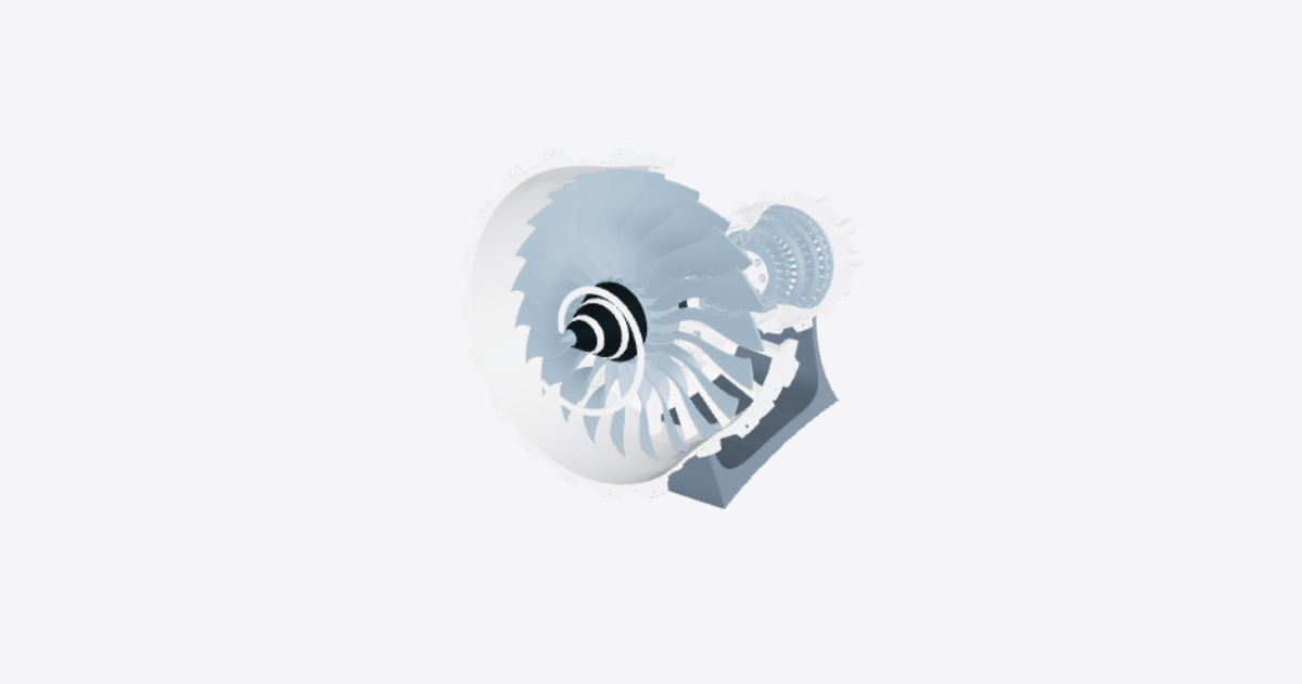
Turbofan engine – 3D model preview

Turbofan engine

Téa · Aerospace · 3D model · Updated 30 Oct 2026

Open in 3D

  • Procedures2shared publicly
  • Views0all time
  • Rating–No ratings yet
  • Likes0from the Community

0 comments

Procedures

Main Fan and Core Bearing Maintenance

Maintenance · 15 steps · No ratings yet

15 steps
  1. Overview

    This guide shows how the main fan and the core bearing come out of a turbofan engine, are inspected, and go back in. It uses a simplified educational model: for real engines, always follow the manufacturer's maintenance manual.
  2. Safety Isolation

    Verify engine stand locks are engaged and isolate FADEC power.
  3. Outer Fan Casing Removal

    Unbolt the outer bypass duct to expose the engine core.
  4. Spinner Cone Removal

    Remove the retaining hardware holding the nose spinner in place at the front of the engine to expose the fan rotor hub.
  5. Fan Blade Extraction

    Remove the Stage 1 fan blades carefully from the central shaft for further inspection.
  6. Fan Inspection

    Perform microscopic inspection of the leading edges for aerodynamic wear, erosion, or foreign object damage (FOD).
  7. Low-Pressure Compressor (LPC) Extraction

    Pull the low-pressure compressor spool forward off the main shaft splines to separate it from the deeper core components. Carefully make sure the front bearing slides out with the shaft, while the inner core bearing remains. 
  8. Core Bearing Tool Engagement

    Use and position the specialized mechanical bearing puller tool into the center bore of the core frame. Expand the tool jaws so they firmly grip the backside of the inner ring of the bearing. Apply localized heat to the surrounding housing to allow for smooth thermal expansion.
  9. Mechanical Extraction of Core Bearing

    Turn the central forcing bolt on the mechanical puller. This smoothly draws the bearing straight out of its tight, press-fit interference seat.
  10. Inspect Core Bearing

    Clean the bearing thoroughly in an approved solvent. Perform a visual and tactile inspection under high lighting. Check the rollers and races for spalling (flaking metal), pitting, scoring, or heat discoloration. If defects are found, discard and unbox a new replacement bearing.
  11. Reinstall the Core Bearing (Thermal Installation)

    Warm the bearing housing slightly with the induction heater (or chill the new bearing) so the press fit opens up, then slide the bearing straight back into its static housing until it seats flush against the rear shoulder. Let it return to room temperature before going on.
  12. Reinstall the Low-Pressure Compressor

    Carefully slide the LPC shaft backward through the hollow center of the high-pressure spool. The shaft splines will slide through the center of the core bearing while the front bearing will seat back into its forward structural housing location on the shaft.
  13. Reinstall Fan and Spinner Nose Cone

    Slide the fan blades back into their respective dovetail slots on the rotor disk, and position and screw tightly the spinner nose cone to ensure the cone remains secure under high operational RPMs.
  14. Re-install the Outer Fan Casing

    Reinstall the outer bypass duct casings over the core module. 
  15. Final checks

    Turn the fan slowly by hand: it should rotate freely, without rubbing or unusual noise. Check that no tools or loose hardware are left in the engine, then record the work done.

Components Inspection

Quality Control · 8 steps · No ratings yet

8 steps
  1. Prepare the turbofan for inspection

    Place the turbofan in a stable inspection condition. Confirm it is de-energized, cooled, depressurized, and secured against rotation or movement before touching or rotating any assembly.

    Clean accessible surfaces enough to expose cracks, corrosion, impact marks, missing hardware, fluid leakage, rubbing, or heat discoloration.

  2. Inspect fan casing and supports

    Inspect the fan casing and support structure for dents, cracks, deformation, loose mounts, missing hardware, rubbing marks, corrosion, and foreign object damage.

    Replacement or repair is required if: structural cracks are present, the casing is distorted, supports are loose or damaged, rub marks indicate abnormal rotor contact, or hardware cannot be secured correctly.

  3. Inspect fan and low-pressure spool components

    Inspect fan/low-pressure spool components for blade impact damage, cracks, bent or missing material, leading-edge erosion, abnormal wear, looseness, imbalance indicators, and evidence of rubbing against the casing.

    Replacement or repair is required if: any blade or spool component is cracked, severely eroded, bent, loose, missing material beyond approved limits, or shows abnormal rubbing/contact.

  4. Inspect high-pressure spool components

    Inspect high-pressure spool components for cracks, rubbing, heat distress, erosion, distortion, loose features, and signs of imbalance or contact with adjacent casings.

    Replacement or repair is required if: cracks, distortion, excessive erosion, abnormal contact marks, looseness, or heat-related damage are found.

  5. Inspect core casings and combustion section

    Inspect the core casings and combustion section for cracking, burn-through, warping, missing fasteners, leakage paths, heat discoloration, loose liners, and damaged interfaces.

    Replacement or repair is required if: cracks, burn-through, severe heat distress, loose or missing attachment points, casing distortion, or leakage at critical joints is found.

  6. Inspect nozzle section

    Inspect the nozzle section for cracks, distortion, missing or loose hardware, erosion, heat damage, and blockage or deformation of flow paths.

    Replacement or repair is required if: the nozzle is cracked, distorted, severely eroded, loose, blocked, or heat damaged beyond approved limits.

  7. Inspect bearing assemblies

    Inspect all bearing assemblies for looseness, rough rotation, abnormal play, discoloration from overheating, contamination, corrosion, lubricant loss, leakage, and damaged retainers or seats.

    Replacement is required if: the bearing feels rough or seized, has excessive play, shows heat damage, contamination, corrosion, leakage, or cannot retain correct lubrication.

  8. Inspect stand and mounting interfaces

    Inspect the stand and mounting interfaces for cracks, loose or missing fasteners, deformation, corrosion, misalignment, and unstable support conditions.

    Replacement or repair is required if: the stand or mounting points are cracked, bent, unstable, corroded beyond acceptable limits, or cannot safely support the turbofan.